Abstract
This publication is a comprehensive technical guide to the IBM Power S1112, the entry-level scale-out server in the IBM Power11 family. It covers system architecture, processor and memory design, RAS capabilities, PCIe Gen4 expansion, NVMe storage, and workload planning for distributed, branch-office, and edge environments. Topics also include AI acceleration through Matrix Multiply Assist (MMA), operating system deployment with IBM i, AIX, and Linux, PowerVM virtualization, HMC system management, firmware lifecycle management, and hybrid cloud integration with IBM Power Virtual Server (PowerVS) and Red Hat OpenShift.
This content is intended for IT architects, systems administrators, technical sales professionals, and infrastructure specialists responsible for planning, deploying, and managing IBM Power11 environments.
Authors
Fiona Tang, Nicole Nett, Jordan Antonov, Mike Davis, Dannia Fajardo Madrigal, Gayathri Gopalakrishnan, Jean-Manuel Lenez, Dean Mussari, Sreevidhya Nair, Nnamdi Okore-Affia, Nageswara Sastry Renduchintala, Girish Shrigiri, Tsvetomir Spasov and Prerna Upmanyu
- Introduction
- IBM Power S1112 platform overview
- IBM Power S1112 Architecture
- IBM Power S1112 Processor configuration Options
- Power11 Processor Characteristics
- IBM Power S1112 Memory Architecture
- IBM Power S1112 Capacity and Performance Considerations
- IBM Power S1112 System Interconnects and Internal Bandwidth
- I/O and Storage overview
- IBM Power S1112 Physical Design
- IBM Power S1112 Form Factor and Dimensions
- Power and Cooling
- Reliability, Availability, and Serviceability (RAS)
- Comparison with Other Power11 Systems
- Architectural Trade-offs: IBM Power S1112 Scale-out vs Larger Power Systems
- IBM Power S1112 Deployment Considerations
- IBM Power S1112 Architecture overview
- I/O architecture and connectivity
- AI and Workload Capabilities
- System management and operations
- Operating Systems
- Enterprise Solution
- Serviceability and Maintenance
- Virtualization and LPAR Management
- Hybrid Cloud Solutions
- Notices
IBM Power S1112 Architecture
IBM Power S1112 Processor configuration Options
Processor Options overview
The IBM Power S1112 is available with two Power11 processor module configurations designed to address different performance and workload requirements while maintaining the same single-socket system architecture.
The rack-mounted S1112 (MTM 9242-21B) supports either a 10-core Power11 processor module or a 4-core Power11 processor module, both implemented as an integrated Open System Compute Module (ioSCM). The deskside tower version (MTM 9242-21T) is available with the 4-core configuration only.
Processor Specification Comparison
10-Core Processor Module
The 10-core processor option is optimized for customers requiring greater compute density and workload consolidation. It features 10 active processor cores, 10 MB of L3 cache, a fixed operating frequency of 3.05 GHz, and a maximum operating frequency of up to 4.0 GHz. This configuration is designed for higher-performance environments and supports a processor power envelope of up to 285 W.
4-Core Processor Module
The 4-core processor option provides a cost-effective entry point into the Power11 platform. It includes 4 active processor cores, 8 MB of L3 cache, a fixed operating frequency of 3.60 GHz, and a maximum operating frequency of up to 4.0 GHz. Despite having fewer cores, this configuration is well suited for workloads that benefit from strong single-thread performance, due to its higher base frequency. This configuration operates within a 230 W power envelope.
Shared Processor Features
Both processor options support the following:
- IBM Power11 architecture
- Integrated Open System Compute Module (ioSCM) packaging
- Power Save frequency of 2.4 GHz
- Dynamic frequency scaling through WOF (Workload Optimized Frequency)
- Maximum operating frequency up to 4.0 GHz
- Enterprise-class reliability, availability, and serviceability (RAS)
- Compatibility with IBM AIX, IBM i, and Linux on Power
For guidance on selecting between the two configurations based on workload characteristics, see Architectural Trade-offs: IBM Power S1112 Scale-Out vs Larger Power Systems.
Power11 Processor Characteristics
Introduction
The IBM Power11 processor is the core technology foundation of the Power S1112 server. It continues a design philosophy IBM Power processors have followed for decades: deliver high throughput, enterprise reliability, advanced virtualization, and secure computing — together, not as separate add-ons.
Unlike processors designed primarily for single-user workloads, Power processors are optimized for large transaction processing, database-intensive applications, highly virtualized environments, mission-critical enterprise workloads, and continuous availability. That focus shapes the architecture in four consistent ways: doing more useful work per processor core, keeping execution units continuously utilized, moving data efficiently between processor and memory, and detecting and recovering from hardware faults before they become outages.
Power11 Processor Design Philosophy
Enterprise applications behave very differently from desktop workloads. A single business application typically contains thousands of simultaneous activities rather than one user waiting on one task at a time. A banking application makes this concrete:

Thousands of transactions like this one may be happening at the same moment across the same server. The Power11 processor is built specifically to handle that kind of concurrent load, using powerful cores, multiple hardware threads, large cache structures, high memory bandwidth, and dedicated reliability logic — none of which matter much for a single isolated task, but all of which matter enormously at enterprise scale.
Processor Core Architecture
A Power11 processor consists of multiple high-performance cores, each acting as an independent execution engine, with a layer of shared resources underneath them all:
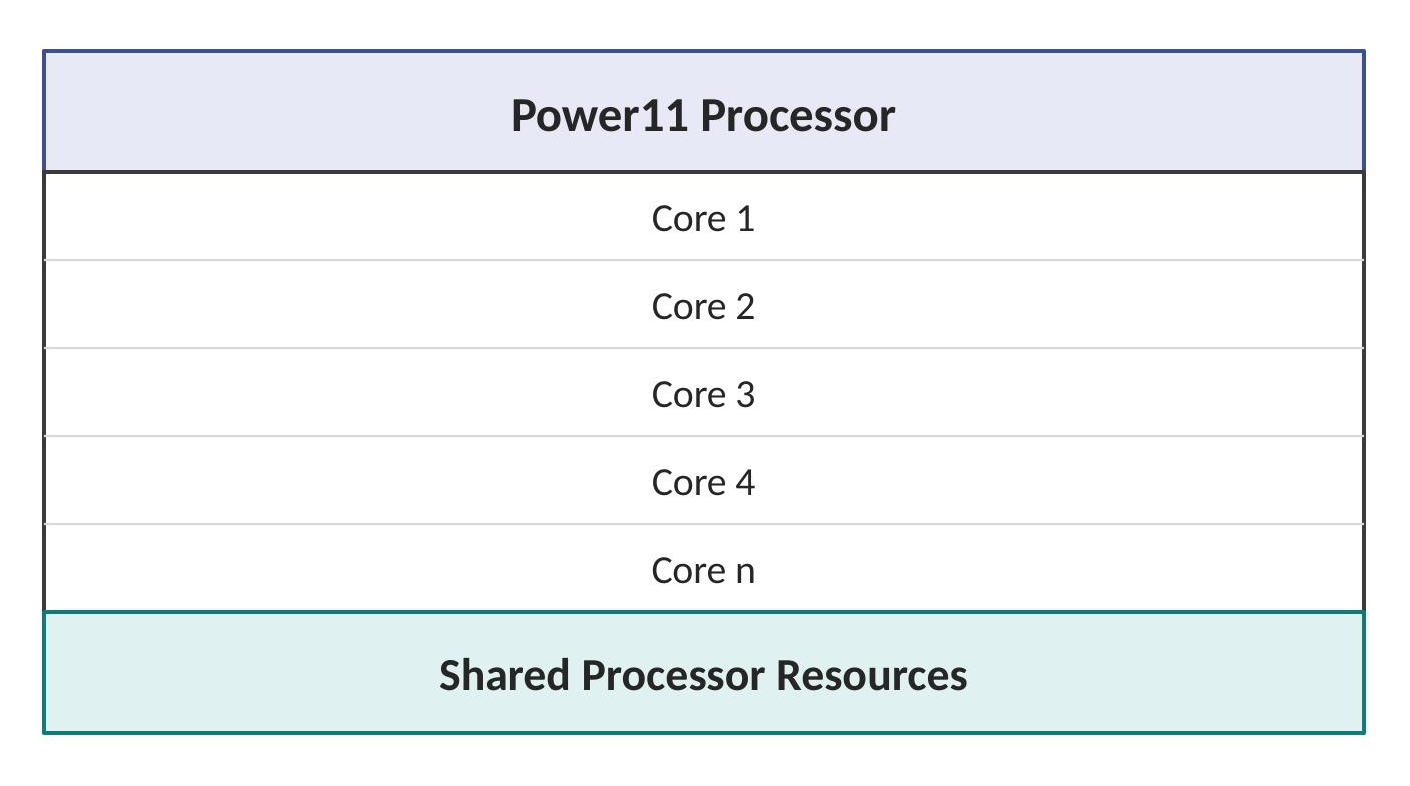
Each individual core contains instruction processing units, integer execution units, floating-point units, vector processing units, branch prediction logic, cache access components, and thread management logic — a complete execution pipeline in miniature, repeated across every core on the chip.
Instruction Execution Flow
When an application runs, its instructions pass through several distinct processor stages before completing:

The processor's job throughout this pipeline is to keep every stage busy simultaneously rather than letting any one stage sit idle. The objective is simple to state: maximum instructions completed per clock cycle.
Simultaneous Multithreading Enhancement
One of the strongest characteristics of IBM Power processors is Simultaneous Multithreading, or SMT. Traditional processors can waste cycles when a workload stalls waiting on memory access, I/O completion, or data availability — the core sits there with nothing productive to do until the wait resolves.

While one thread waits, another thread uses the processor resources that would otherwise sit idle. That single mechanism delivers four compounding benefits: increased throughput, more users supported per server, better resource efficiency, and higher virtualization density — all from extracting useful work out of cycles that traditional designs simply discard.
Cache Hierarchy
Processor speed is significantly faster than memory speed, and that gap is exactly the problem cache memory exists to solve — by storing frequently accessed information close to the processor, Power11 avoids paying the full cost of a memory round trip for every single access.
Level 1 Cache (L1)
L1 sits closest to the processor core. It's the smallest cache level, the fastest to access, and it stores the immediate instructions and data the core needs right now:

Its purpose is narrow and specific: reduce delay during instruction execution.
Level 2 Cache (L2)
L2 is the next layer out — larger than L1, slightly slower, and built to hold additional working data that doesn't fit in L1's tighter footprint:
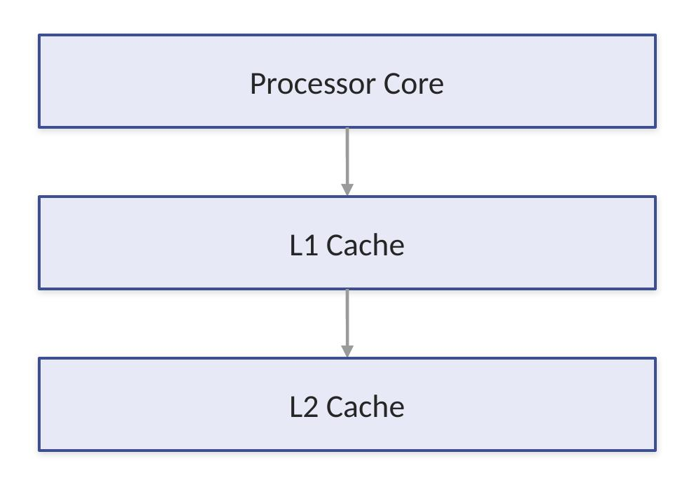
That extra capacity reduces memory requests and improves workload performance, catching data L1 couldn't hold before the processor has to reach all the way out to main memory.
Level 3 Cache (L3)
L3 is a large cache shared across all cores on the chip, rather than dedicated to any single one:

Because every core can draw from the same pool, L3 particularly improves multicore workloads, reduces overall memory traffic, and helps database applications specifically — workloads where multiple cores are often working on related data at the same time.
Memory Access Optimization
A processor frequently requires data from memory, and the performance goal underneath the entire cache hierarchy is the same: find the data as high in the hierarchy as possible, since every level down adds latency.

Branch Prediction Technology
Applications are full of decision points — an if/else branch checking something like whether an account balance covers a requested transaction amount is a perfectly ordinary example. The processor doesn't wait for that decision to fully resolve before acting; it predicts the likely path in advance.

When the prediction is right, the processor effectively gets ahead of the decision for free. When it's wrong, the work done on the mispredicted path has to be discarded and restarted — which is exactly why advanced branch prediction is worth real engineering investment: getting it right consistently is a direct application speed advantage.
Vector and Matrix Processing
Modern workloads — analytics, AI calculations, encryption, scientific computing — increasingly require processing large groups of data together rather than one element at a time. Vector processing is built for exactly that pattern.
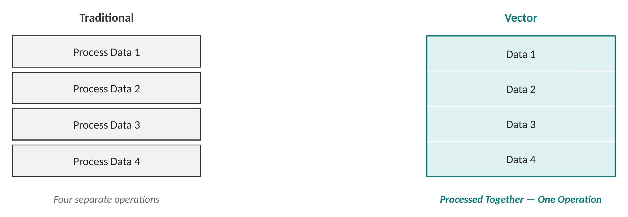
The benefit compounds with data volume: faster calculations, improved AI processing, and better analytics performance, since the processor is doing in one operation what traditional execution would need four separate passes to accomplish.
AI Acceleration Capabilities
Modern enterprise systems increasingly integrate artificial intelligence directly into their workflows — pattern detection, prediction models, automation, and data analysis are no longer specialized, separate workloads. Processor-level acceleration helps in three concrete ways: reducing execution time, improving inference performance, and keeping AI processing close to where the enterprise data already lives.

Security Enhancements
Security in the Power11 isn't bolted on after the fact — it's integrated into the processor design itself, across three distinct areas.
Secure Execution protects workloads while they're actively running, not just at rest.
Firmware Protection ensures a trusted system startup, where each layer in the boot chain validates the one above it before handing off control:

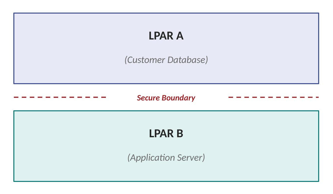
Workload Isolation keeps virtual machines genuinely separated from each other, even when they're sharing the same physical processor:
Reliability Features Inside Processor
Enterprise processors have to keep operating even when faults occur — and Power11's reliability capabilities are built around three connected functions.
Error Detection runs continuously: hardware checks itself rather than waiting for a visible symptom to surface.
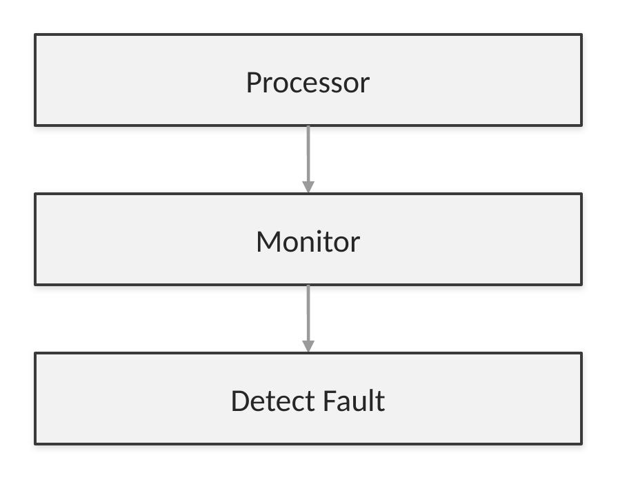
Error Correction handles certain failures automatically, without the application ever noticing:
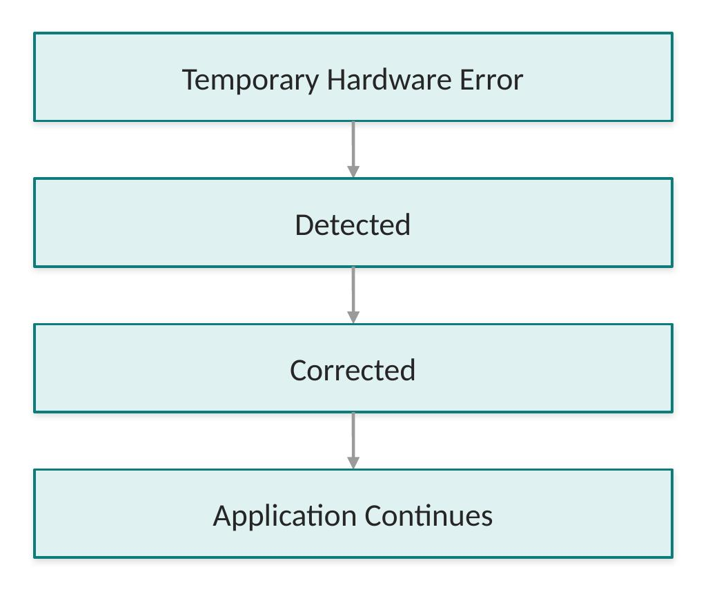
Fault Isolation means a failing component can be identified and contained without affecting the entire system — the failure stays local rather than cascading.
Performance per Core Advantage
Power architecture focuses on maximizing useful work from each individual core, not simply maximizing the number of cores on the chip. Real performance depends on core capability, SMT efficiency, cache size, memory bandwidth, and I/O capability working together — not just "number of cores" taken in isolation, which is a far less reliable predictor of actual enterprise workload performance than it might seem.
Enterprise Workload Optimization
Power11 processors are optimized for several distinct categories of enterprise workload, each stressing different parts of the architecture.
Database systems — Db2, Oracle, and similar platforms — benefit from large cache, high memory bandwidth, and strong transaction throughput.
Business applications like SAP, ERP, and financial applications need consistent response time and high availability above almost everything else, since unpredictable latency is often worse than moderately slower-but-consistent performance.
Cloud workloads benefit from supporting many virtual servers at once, secure isolation between them, and dynamic resource allocation that can shift as demand changes.
IBM Power S1112 Memory Architecture
Introduction
The memory subsystem is one of the most important architectural components of the IBM Power S1112 server. Modern enterprise workloads aren't limited only by processor speed — the ability to rapidly move large amounts of data between processor cores and memory has a direct, measurable effect on application performance.
The Power11 memory architecture is built to deliver high bandwidth, low latency, large workload capacity, data protection, continuous availability, and enterprise reliability all at once. The memory subsystem works in close partnership with the Power11 processor to keep execution units supplied with data and minimize the time those execution units spend waiting.
Importance of Memory in Enterprise Systems
Applications continuously move data between the processor, memory, storage, and network. A simplified view of that flow makes a useful principle visible:
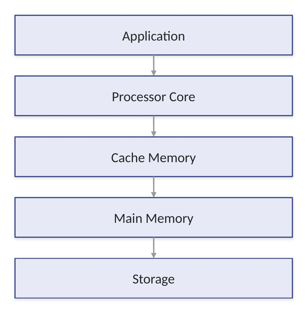
The closer data sits to the processor, the faster the system can actually process work — which is the entire reasoning behind the multi-tier memory hierarchy described later in this section.
Processor and Memory Relationship
The processor executes instructions, but those instructions and the data they operate on have to come from memory first. A database query makes this dependency concrete:

If memory access is slow, even the most powerful processor cores remain idle, simply waiting. That's why IBM Power systems focus heavily on memory throughput, efficient access paths, and reliability — a processor's theoretical performance is only ever as good as the memory feeding it.
Memory Hierarchy
The Power S1112 uses a hierarchical approach to data access, with each level trading off speed, size, and cost against the level above it:

This hierarchy isn't arbitrary — it reflects a basic engineering reality. The fastest storage technology available is also the most expensive and the hardest to make large, so systems use a small amount of very fast storage close to the processor and progressively larger, slower, cheaper storage further away.
System Memory Design
The main memory subsystem provides workspace for operating systems, applications, databases, virtual machines, and file cache. PowerVM manages how that physical memory is actually divided up across all of them:

PowerVM is the layer responsible for managing allocation of physical memory resources across every partition and workload sharing the server.
Memory Channels
Modern processors use multiple memory channels specifically to increase bandwidth. A single channel design routes all traffic through one shared path:
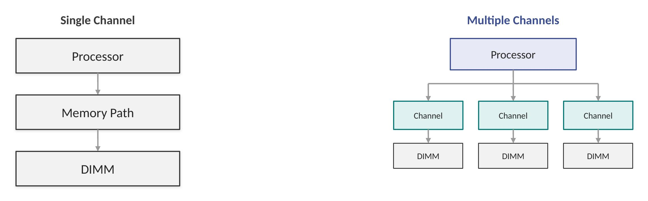
A multi-channel design instead gives the processor several independent paths to work with simultaneously:
That parallelism is what delivers the real advantages: more simultaneous data movement, reduced bottlenecks, and better processor utilization, since the processor is no longer waiting behind a single shared path.
Memory Bandwidth
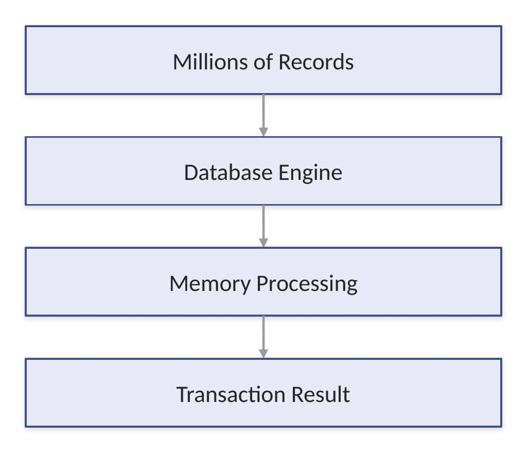
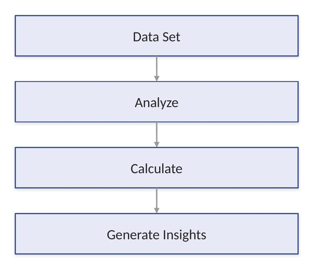
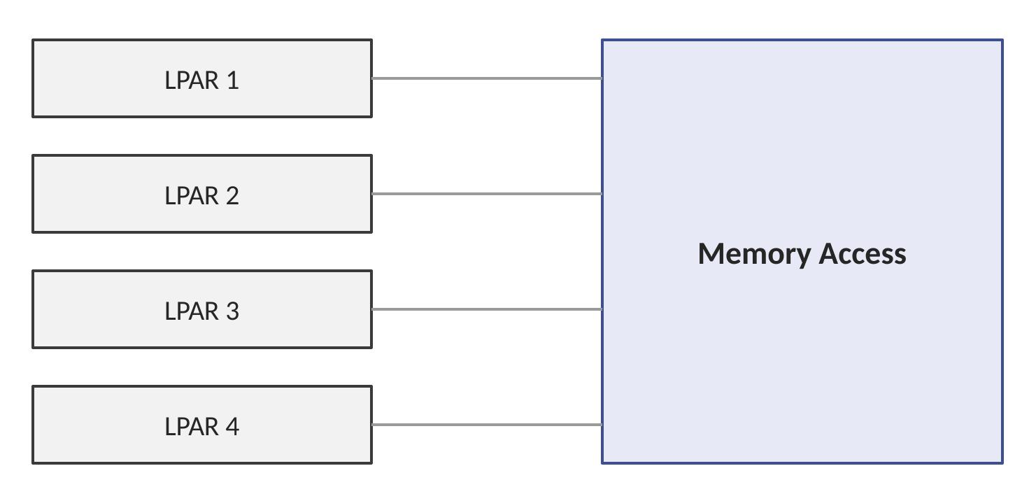
Memory bandwidth represents how much data can move between processor and memory per second, and different workload types depend on it in different ways.
Databases push large volumes of records through memory on the way to a result:
Analytics workloads require continuous memory movement as large datasets are processed:
Virtualization adds a different kind of pressure — multiple partitions all requiring memory access at the same time, not sequentially:
Memory Allocation with PowerVM
PowerVM provides advanced memory management, and a concrete example shows how that plays out in practice. Take 128 GB of installed physical memory — it can be divided across partitions according to actual workload need rather than split evenly by default:
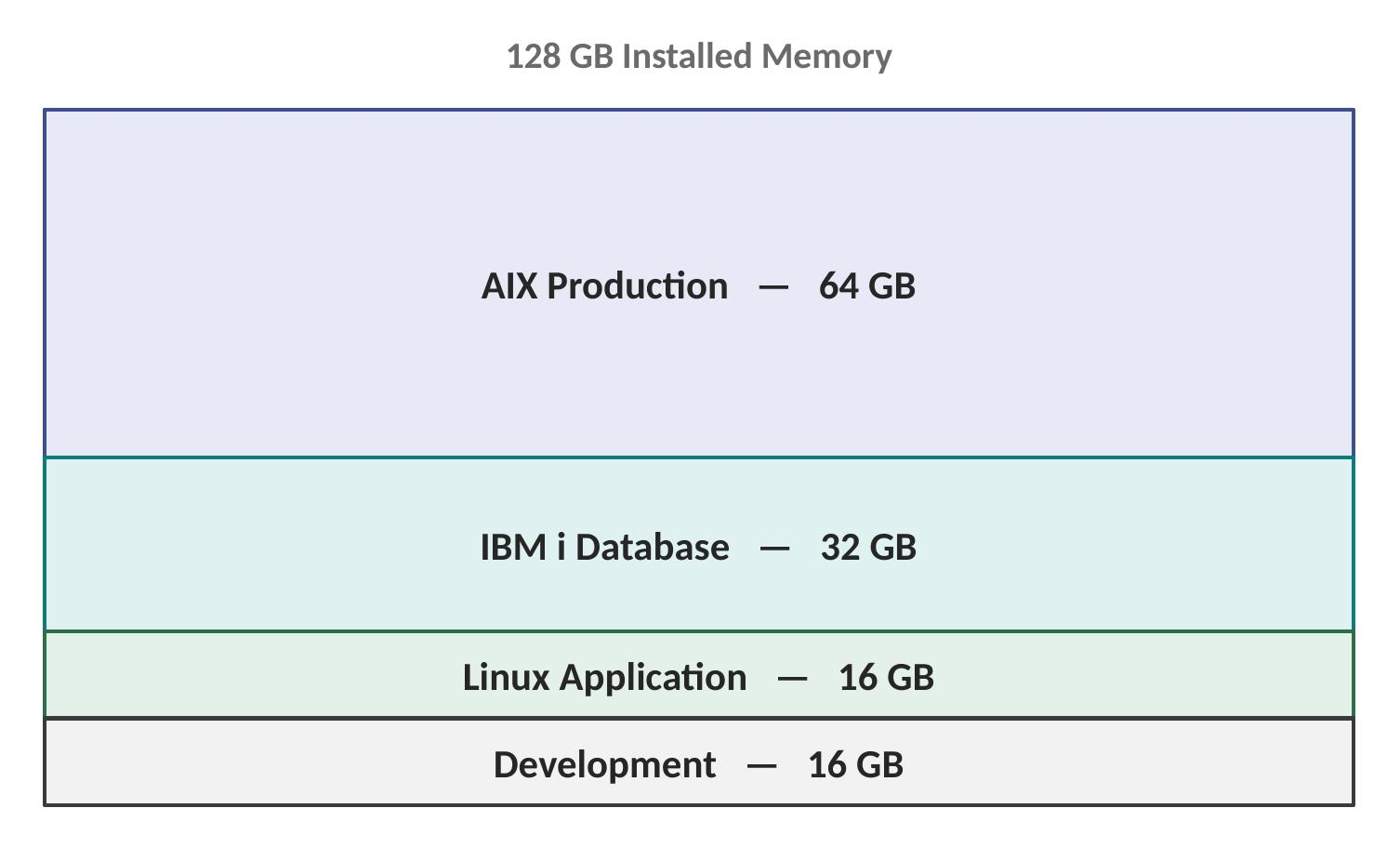
These allocations aren't fixed forever — resources can be adjusted as workload needs change over time.
Dynamic Memory management
Power architecture allows real memory flexibility instead of permanently assigning fixed resources to each partition. What a system needs can shift meaningfully within a single day:

Administrators can dynamically adjust allocations to match these shifting patterns, which improves utilization, reduces waste, and produces better workload response than a static, fixed-allocation approach ever could.
Active Memory Sharing Concept
In virtualized environments, memory can be shared far more efficiently than the traditional model allows. Under a traditional fixed-allocation model, each LPAR gets a set amount of memory whether it's using all of it or not:

A shared approach instead draws from a common pool:
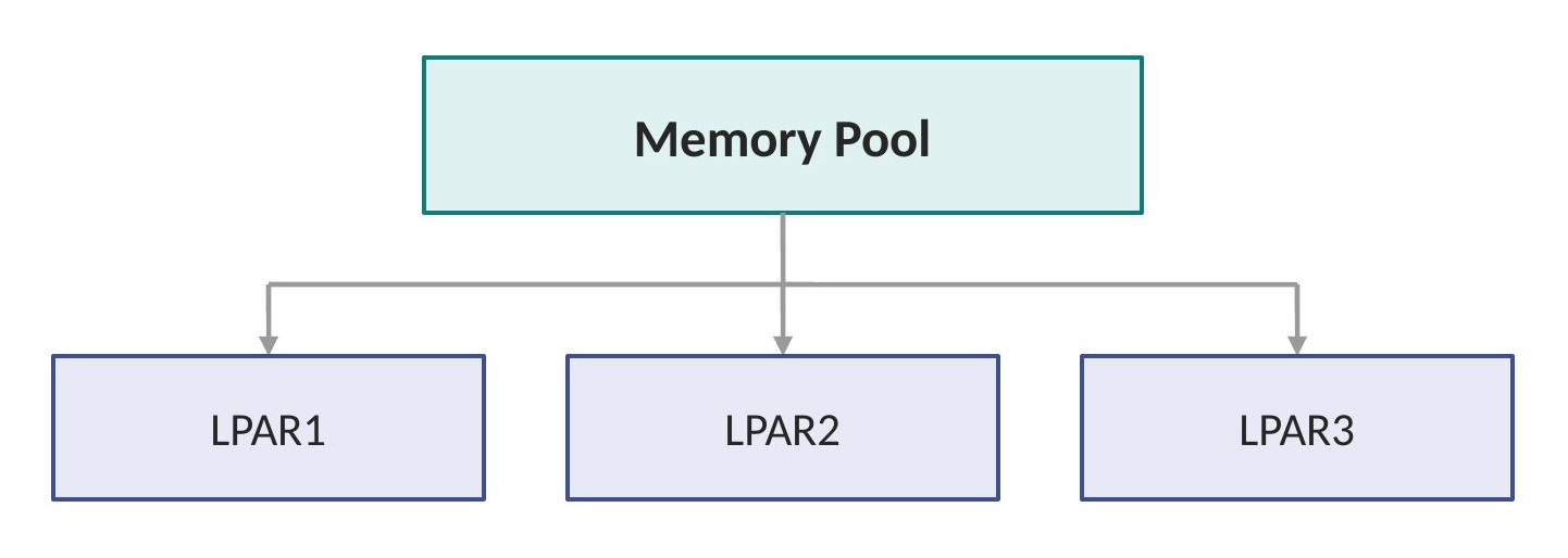
That pooled model delivers better consolidation, supports more workloads per server, and gives administrators genuinely flexible capacity — memory that's idle in one partition becomes immediately available to another, rather than sitting unused.
Memory Reliability Requirements
Enterprise servers cannot tolerate memory corruption. A single memory error can cause application failure, database corruption, or a full system outage — which is why Power systems include advanced memory protection rather than treating memory reliability as an afterthought.
Error Checking and Correction (ECC)
ECC memory detects and corrects memory errors automatically, working on both the write path and the read path. When data is written, a correction code is generated and stored alongside it:
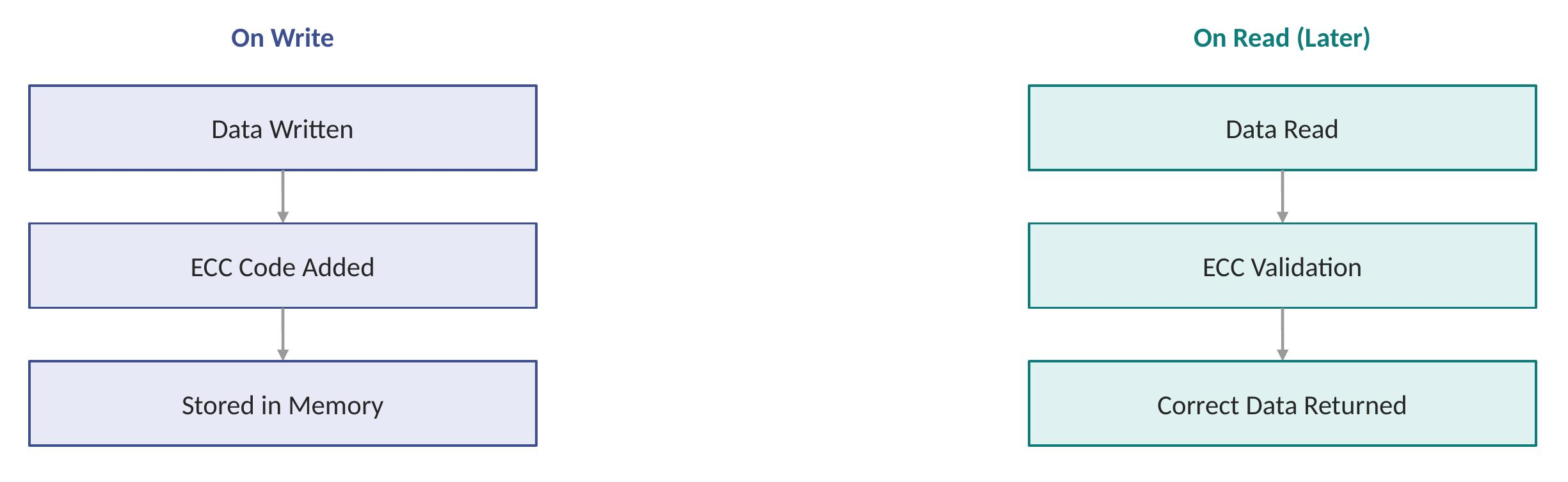
Later, when that data is read back, the stored code is used to validate it before the processor ever sees it:
This combination is what prevents silent data corruption — the kind of error that doesn't crash anything but quietly produces a wrong answer — while also improving overall reliability and supporting continuous operation.
Chipkill Technology
Chipkill is an advanced IBM memory reliability technology that changes what happens when an entire memory chip fails, not just a single bit. Under a traditional model, that kind of failure goes straight to the application:
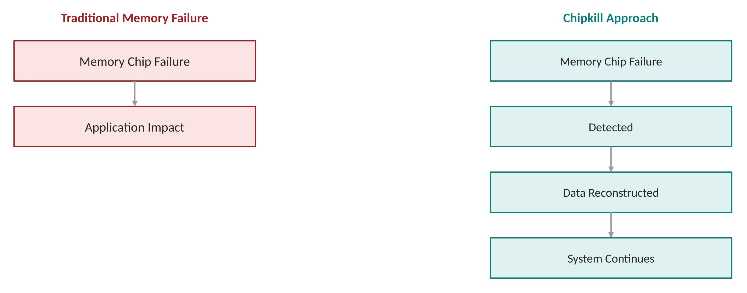
Chipkill's approach inserts detection and recovery in between:
The practical advantages are significant: higher availability, real protection from component-level failures rather than just bit-level errors, and fewer unplanned outages overall.
Memory Error Handling Flow
Put together, the typical reliability process for a memory error follows a consistent six-step path:
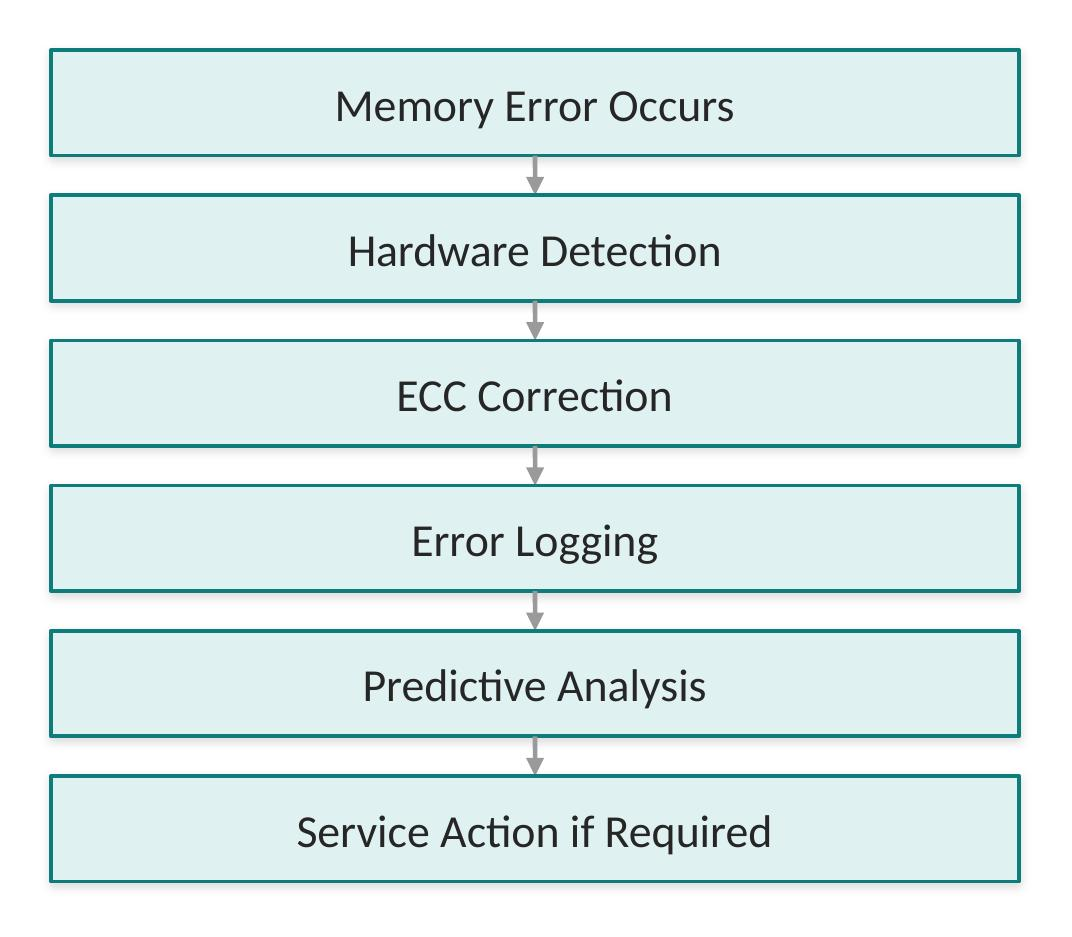
The goal threading through every step is the same one that shows up throughout this book's treatment of Power reliability: fix problems before they become outages.
Memory and Workload Planning
Correct memory sizing depends heavily on workload type — there's no single right answer that applies across IBM i, AIX, and Linux equally.
IBM i workloads need to account for database size, number of users, and batch processing. IBM i in particular benefits from larger memory allocations because its integrated database uses memory extensively as a normal part of operation, not just under heavy load.
AIX workloads need to factor in application requirements, database buffer pools, and middleware needs — concretely, things like Oracle SGA sizing, Db2 buffer pools, and WebSphere heap allocation.
Linux workloads bring their own planning considerations: containers, application services, AI workloads, and open-source databases, each with different and often less predictable memory growth patterns than traditional enterprise applications.
Memory Performance Best Practices
A handful of practices consistently separate memory configurations that perform well under real load from ones that look adequate on paper:
- Balance processor and memory capacity
- Avoid processor-rich but memory-poor configurations
- Size database memory carefully
- Monitor memory utilization
- Keep growth requirements in planning
- Follow IBM memory placement rules
- Use supported memory configurations
Common Memory Bottlenecks
Insufficient memory has recognizable symptoms: high response time, excessive paging, slow database queries, and increased disk activity. The underlying mechanism is straightforward once you see the chain:

Once an application starts paging to disk because physical memory runs out, the performance hit shows up everywhere downstream — which is exactly why memory bottlenecks tend to look like broader application slowness rather than an obviously memory-related problem.
IBM Power S1112 Capacity and Performance Considerations
Introduction
Capacity planning and performance optimisation are critical activities when deploying the IBM Power S1112. A successful deployment is not achieved by selecting the highest processor or memory configuration — it requires a balanced system where processor resources, memory capacity, storage performance, network bandwidth, and virtualisation configuration work together efficiently.
This topic provides practical guidance on sizing the S1112 across its most common workload types: IBM i business applications, AIX database environments, Linux container and AI workloads, and mixed virtualised deployments. It also covers monitoring tools by operating system and the utilisation targets that distinguish a well-sized system from one that is either over-provisioned or heading toward a capacity problem.
A bottleneck in any one subsystem constrains overall system performance, regardless of how well-provisioned the others are.
Capacity Planning Methodology
Before configuring a Power S1112, analyse two dimensions: current workload and projected growth.
Current workload questions to answer:
- What applications will run, and on which operating systems?
- How many users, and what is the peak transaction volume?
- What databases are involved, and what are their memory and storage profiles?
Growth planning — enterprise systems are typically purchased for a three-to-five year horizon. Size for where the workload will be, not only where it is today. A common planning pattern:
CPU Sizing
Utilisation Philosophy
Traditional commodity server sizing targets conservative utilisation of 15–20%, leaving most processor capacity idle to absorb unpredictable spikes. IBM Power systems are engineered to operate efficiently at significantly higher sustained utilisation — typically 60–80% for suitable workloads — without the performance degradation seen on commodity platforms at similar levels.
This higher sustainable utilisation is made possible by SMT capability, PowerVM scheduling, and the advanced Power11 processor design.
Processor sizing depends on application type, transaction volume, thread behaviour, and virtualisation design. Resources should be assigned based on business priority.
Dedicated vs Shared Processors
Dedicated processors are recommended for critical databases, workloads requiring predictable latency, and environments with per-core software licensing requirements (for example, an Oracle Database LPAR with dedicated cores).
Shared processors are recommended for multiple small workloads, development environments, and variable-demand workloads. Shared pools improve utilisation and reduce idle capacity across the server.
Memory Sizing
Memory sizing is often more important than processor sizing. Insufficient memory forces the operating system to page active working-set data to storage — a condition that degrades application response times by orders of magnitude and is one of the most common root causes of unexplained performance problems in production Power environments.
Database Memory
Databases benefit greatly from memory because frequently accessed data can be served without disk access. Key memory consumers by database engine:
IBM Db2 — buffer pools, sort operations, query processing, and temporary tables. Correct sizing improves query speed, transaction rate, and response time.
Oracle Database — the System Global Area (SGA) and Program Global Area (PGA) are the primary sizing targets. Performance depends on balancing database memory, processor capacity, and storage speed together.
AI Workloads
AI workloads require substantial memory bandwidth for mathematical processing and large dataset movement. The Power11 Matrix Math Acceleration (MMA) units — 8 per core, double the count in Power10 — provide on-processor acceleration for matrix multiply operations that underpin neural network inference. This allows the S1112 to serve AI inference workloads directly on the same platform as the enterprise data, avoiding the latency and data movement cost of externalising inference to a separate GPU-attached system.
Storage Performance
Storage performance affects database response time, application startup, and batch processing throughput. Three metrics drive storage sizing decisions:
NVMe storage improves all three: lower latency through a shorter PCIe-direct path, higher IOPS through deep parallel queues, and increased throughput compared to traditional storage controllers.
Network Performance
Modern applications communicate continuously. Network sizing must account for user and application traffic, backup traffic, replication, and storage connectivity. Network bottlenecks can limit application performance even when CPU, memory, and storage are well-provisioned — plan and monitor network capacity as a first-class resource alongside the others.
Virtualisation Performance
PowerVM allows multiple workloads to share a single server. Virtualisation planning covers virtual CPU entitlement, memory allocation per LPAR, virtual I/O design, and shared resource pools.
VIOS (Virtual I/O Server) provides shared I/O resources across LPARs, delivering adapter sharing, flexible configuration, and simplified management. VIOS sizing and redundancy must be included in the overall capacity plan.
Workload Types and Resource Profiles
Performance Monitoring
Capacity planning does not end at installation — continuous monitoring is required to detect drift before it becomes a production problem.
Monitoring tools by operating system:
Key metrics to track continuously:
Capacity Planning Best Practices
- Size for the business workload profile, not only hardware specifications
- Keep CPU, memory, and storage balanced — a bottleneck in one negates the others
- Plan for 3–5 years of growth from day one
- Separate critical workloads onto dedicated or prioritised resources
- Monitor continuously after deployment, not only during initial sizing
- Use PowerVM resource flexibility to adjust allocations as workloads shift
- Avoid unnecessary over-allocation that reduces the shared pool available to other LPARs
- Review performance data on a regular cadence and adjust capacity before problems surface
IBM Power S1112 System Interconnects and Internal Bandwidth
Introduction
The performance of a modern enterprise server depends on more than processor speed. It depends just as much on how efficiently information moves between internal system components — a fast processor sitting behind a slow internal path is still a slow server.
The IBM Power S1112 Power11 one-socket scale-out server is built around a high-performance internal communication architecture that connects processor cores, the cache subsystem, memory, PCIe adapters, storage devices, network interfaces, and virtualized resources. The goal behind all of it is simple to state and hard to deliver: move data quickly, reliably, and securely with minimum latency.
Understanding Internal Data Movement
Every application transaction requires communication between hardware components, often more hops than people expect. A single database query, for example, touches several distinct components before a response ever reaches the user:
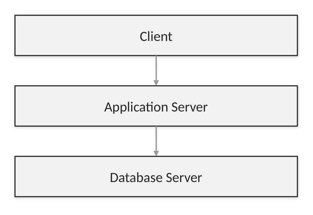
Each step in that chain depends on the efficiency of the internal server fabric. A slow communication path creates a bottleneck even if the processor itself is powerful — which is exactly why interconnect design gets its own dedicated treatment rather than being an afterthought to processor selection.
System Interconnect Architecture overview
The Power S1112 architecture can be viewed as a layered collection of interconnected components, with the system data fabric acting as the backbone that everything else connects through:

That fabric is what provides the communication backbone tying the rest of the system together — without it, each component would essentially be an island.
Processor Internal Fabric
Inside the Power11 processor itself, multiple components have to communicate constantly: processor cores, cache, memory interfaces, and I/O controllers. All four cores share a single internal fabric that routes their requests onward to cache and memory.

That internal processor fabric is specifically optimized for low latency, high throughput, and parallel communication — three properties that matter more, not less, as core counts increase.
Importance of Bandwidth
Bandwidth represents how much information can move through a connection in a given period of time. The easiest way to picture it is the same fixed amount of data being pushed through paths of different widths.

Enterprise workloads require high bandwidth specifically because thousands of operations occur simultaneously. A path that's adequate for occasional, isolated requests can become a serious constraint the moment real concurrent load arrives.
Processor-to-Memory Communication
One of the most heavily used data paths in the entire system runs directly between the processor and memory:

Applications continuously access memory, and the pattern looks different depending on the workload. A database workload tends to follow a tight read-process-write cycle:
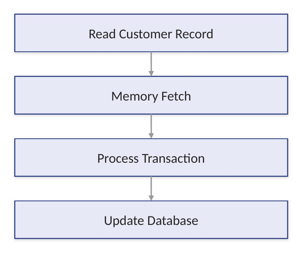
An analytics workload, by contrast, tends to push large datasets through memory toward a calculation engine:
Different as these patterns are, both benefit directly from higher memory bandwidth — it improves database throughput, analytics performance, and virtual machine density all at once, since all three are ultimately competing for the same memory path.
Latency Optimization
Latency simply means delay, and on its own a millisecond rarely seems worth optimizing. But even very small delays become significant once they're repeated billions of times:

This is why Power architecture puts real engineering effort into reducing processor waiting time, memory access delay, and I/O response time — not because any single instance of these delays matters, but because the aggregate at enterprise scale absolutely does.
Cache and Internal Bandwidth
Cache exists, in large part, to reduce pressure on the system interconnects themselves. Without it, every single memory request has to traverse the full path out to memory:

The benefit compounds: less memory traffic, faster processing, and improved scalability as workloads grow, since a well-utilized cache means the shared fabric spends less time handling requests that didn't strictly need to reach memory at all.
PCI Express I/O Architecture
PCI Express (PCIe) is what provides high-speed connectivity between the processor complex and external devices — network adapters, Fibre Channel adapters, NVMe devices, and expansion hardware all connect through it.

PCIe Communication Flow
To see why every layer of that PCIe path matters, consider what happens when an application reads database information from storage:

Each layer in that chain has to operate efficiently — a slowdown at the PCIe controller is just as disruptive to the application as a slowdown at the storage device itself, even though they're very different pieces of hardware.
PCIe Bandwidth Considerations
High-speed PCIe delivers more data lanes, higher transfer rates, and reduced bottlenecks — but different workloads stress those capabilities in different ways. Databases need fast reads, fast writes, and low latency above all else — small, frequent operations where delay compounds quickly. Backup operations need something different: high throughput movement of large volumes, since the goal is moving an entire dataset, not completing many small transactions.

Network applications need fast packet processing and low delay, since they're typically handling a continuous stream of smaller units of traffic rather than large bulk transfers.
Adapter Communication Architecture
Adapters are what extend the server's capabilities outward, and the two most common types serve very different purposes. Ethernet adapters handle user connectivity, application communication, and cloud integration:

Fibre Channel adapters are built for SAN storage environments specifically:

That dedicated storage path is what enables enterprise storage connectivity, high availability design, and large database support — qualities that are harder to guarantee on a shared, general-purpose network path.
NVMe Connectivity Architecture
NVMe storage uses high-speed PCIe communication, and the real performance gain comes from removing a layer that traditional storage paths still carry.

That shorter path is what delivers NVMe's headline advantages: lower latency, more parallel operations, and higher overall performance.
Virtualization and Internal Data Flow
With PowerVM, many virtual systems share the same underlying hardware, which means a virtual machine's network traffic still has to find its way to a real physical adapter:
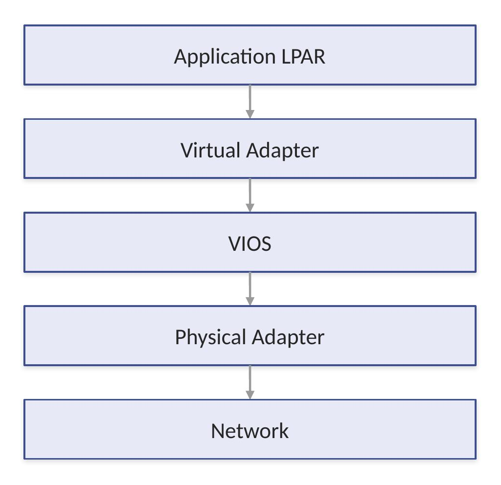
The internal architecture is what ensures virtualized workloads receive efficient access despite that extra layer of indirection — without careful design here, virtualization would simply trade hardware cost savings for a performance penalty.
I/O Virtualization Bandwidth
Multiple LPARs frequently share the same physical adapter rather than each requiring its own dedicated hardware:

PowerVM is responsible for managing traffic flow, resource sharing, and isolation across that shared adapter — three distinct jobs that all have to happen correctly for the sharing arrangement to be safe and performant rather than just cost-effective.
Avoiding System Bottlenecks
Performance problems show up whenever one component can't keep pace with the rest of the system. A fast processor paired with slow storage doesn't average out to acceptable performance — it just means the application waits on storage instead:

A genuinely balanced design requires sufficient processor capacity, adequate memory bandwidth, proper I/O configuration, and correct network sizing, all matched to each other rather than any single component being over-provisioned while another lags behind.
High Availability Considerations
Enterprise designs deliberately avoid single paths, because a single path means a single point of failure. With one adapter between the server and storage, any failure along that path directly impacts the application:

That redundancy is what delivers continuous operation, genuine fault tolerance, and the flexibility to perform maintenance without taking the application down.
Performance Design Best Practices
A handful of practices consistently separate interconnect designs that perform well under real load from ones that look fine on paper:
- Balance CPU, memory, and I/O
- Avoid oversubscribing critical adapters
- Use redundant communication paths
- Monitor I/O utilization
- Separate production and backup traffic
- Design for peak workloads
- Consider future growth
I/O and Storage overview
Processors and memory tend to get top billing in server architecture discussions, but neither matters much if data can't move in and out of the system efficiently. The I/O and storage subsystem of the IBM Power S1112 Power11 one-socket scale-out server is what actually connects the processor complex to the outside world — storage devices, network infrastructure, backup systems, external peripherals, and enterprise SAN environments all depend on it.
Processors execute instructions and memory provides fast data access, but I/O determines how efficiently information actually enters and leaves the system. A genuinely balanced Power S1112 design needs all four pieces working together: fast processors, sufficient memory, high-performance I/O, and a reliable storage architecture. Skimp on any one and the others can't fully deliver.
Role of I/O in Server Architecture
Every business transaction involves I/O activity — often more of it than people expect. Take something as ordinary as online order processing:

That sequence touches I/O twice — once on the network side, once on the storage side — before a response ever makes it back to the customer. Poor I/O performance can slow the entire application even when CPU resources are sitting idle and available, which is exactly why I/O design deserves the same attention as compute.
Power S1112 I/O Architecture overview
The Power S1112 uses a high-speed PCI Express-based I/O architecture. PCIe sits as the connective layer between the processor and everything attached to it:

That PCIe infrastructure is what provides the high bandwidth, low latency, scalable connectivity, and reliable device communication the rest of the I/O subsystem depends on.
PCI Express (pcie) Technology
PCIe is the primary internal communication standard for attaching high-speed devices. Its core idea is simple: dedicated communication lanes between devices and the processor.

What makes PCIe scale well is that multiple lanes can be combined to create wider communication paths — the same logic as a one-lane road versus a multi-lane highway. More lanes simply allow more data to move at once, which is why adapter specifications like PCIe x4, x8, and x16 matter — they describe how many lanes that device gets.

PCIe Adapter Architecture
PCIe adapters are what expand server capabilities beyond what's built in. The most common categories are network adapters and storage adapters, each handling a different part of the I/O picture. Network adapters connect the server to users, applications, cloud platforms, and other servers:
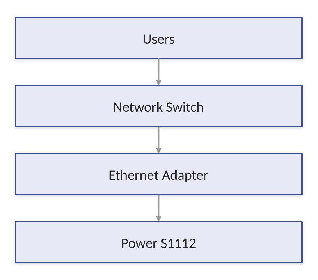
Ethernet Connectivity
Ethernet adapters carry most enterprise networking traffic, but not all of that traffic looks the same. Application traffic moves between the people using the system and the data they're requesting; management traffic carries administration, monitoring, and automation work; and backup traffic can require separate network paths entirely — trying to run backups over the same network as production traffic is a common way to accidentally degrade both. The fix is to keep all three on independent paths:

Separating traffic this way improves both performance and security — a backup job that saturates its own dedicated path can't accidentally starve a production application of bandwidth.
Fibre Channel Storage Connectivity
Enterprise environments commonly rely on SAN storage, and Fibre Channel provides a dedicated communication path purpose-built for that storage traffic, separate from general network traffic.

That dedicated path is what delivers high reliability, large storage capacity, centralized management, and redundant paths — qualities that are harder to guarantee when storage traffic shares a network with everything else.
Storage Area Network (SAN)
A SAN separates storage from individual servers entirely, which is a meaningful shift from the traditional model where each server owns its own disks.

That separation is what makes SAN storage easier to expand, more available, and better suited to enterprise data protection requirements — multiple servers can share the same storage array without each one needing its own dedicated capacity.
Internal Storage overview
None of this rules out internal storage — the Power S1112 still uses local storage resources for operating system installation, boot volumes, local applications, and temporary data. The typical technologies are SSD and NVMe-based devices, chosen specifically because boot and OS-level operations benefit from low latency more than they benefit from shared, centralized capacity.
NVMe Storage Architecture
NVMe (Non-Volatile Memory Express) is built specifically around the strengths of flash storage, and it gets there by removing a layer that older storage paths still carry.

That shorter path translates into reduced latency, higher parallel processing capacity, and faster response overall.
Why Nvme Improves Performance
The difference isn't just a shorter path — it's also how many things that path can do at once. Traditional disks process a small number of queues, which means requests tend to stack up and wait their turn. NVMe is built around supporting many parallel queues instead, so multiple requests can be processed together rather than one after another.
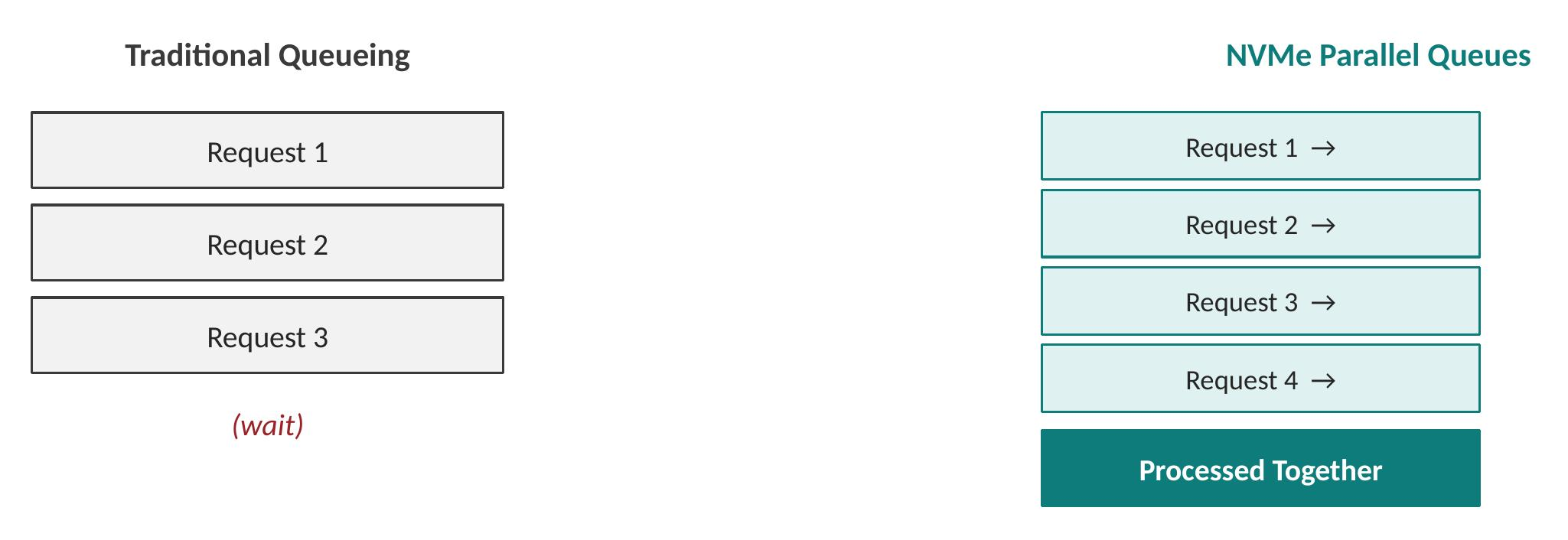
That parallelism is particularly valuable for databases, analytics, and transaction workloads — anything generating a steady stream of concurrent storage requests rather than occasional large ones.
Storage Performance Factors
Storage performance isn't a single number — it's three related but distinct measurements, and conflating them is a common source of confusion when evaluating storage options.
IOPS (Input/Output Operations Per Second) answers "how many storage operations can happen every second?" This matters most for databases, ERP applications, and transaction systems, where the workload is made up of many small, frequent operations.
Latency is the time required for one storage operation to complete:

Lower latency gives faster applications — and it matters most where each individual operation needs to complete quickly, even if the total volume of data is modest.
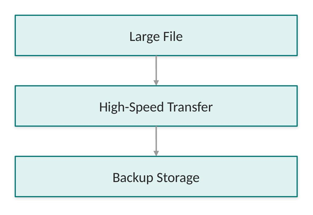
Throughput measures the amount of data transferred, which matters most for backups, reporting, and data warehouses — workloads defined by moving large volumes rather than completing many small operations quickly.
Storage Redundancy
Enterprise systems have to survive hardware failures, and storage paths are no exception. A single, unprotected path is straightforward but fragile — any adapter failure means an outage. The recommended design routes around that risk with two independent adapters and two SAN paths converging on the same storage:
That redundancy delivers three concrete benefits: protection against hardware failure, the ability to perform maintenance without downtime, and meaningfully higher overall availability.
Multipath I/O
Multipathing allows multiple routes to storage and lets the operating system choose between them dynamically.

The real value shows up at the moment of failure. If one path goes down, traffic doesn't stop — it automatically shifts to the surviving path:

Virtual I/O Server (VIOS) Storage Model
PowerVM commonly uses VIOS to virtualize storage, letting multiple operating environments share the same physical storage rather than each requiring dedicated, isolated capacity.

This model brings real practical advantages: adapter sharing reduces the number of physical adapters needed, allocation becomes more flexible, and management gets simpler because there's one virtualized layer to administer rather than many separate physical connections.
Storage Planning by Workload
Storage requirements aren't identical across operating environments. IBM i workloads are shaped by database performance, transaction volume, journaling, and backup windows — a profile that demands low latency and reliable storage paths above almost everything else. AIX commonly runs Oracle, Db2, and various middleware, where SAN design, multipathing, and I/O balancing matter most. Linux environments increasingly run containers, open-source databases, and AI workloads, needing fast storage and flexible expansion as both the workload mix and capacity requirements tend to shift more often than in traditional enterprise applications.
Backup and Recovery Considerations
Storage design has to include recovery planning from the start, not as an afterthought. The key considerations are backup frequency, recovery time objective (RTO), and recovery point objective (RPO) — together these define how much data you can afford to lose and how quickly you need to be back online.

Storage Best Practices
A handful of practices consistently separate storage designs that hold up under pressure from ones that don't:
- Use redundant storage paths
- Separate critical workloads
- Monitor I/O latency
- Avoid storage bottlenecks
- Plan capacity growth
- Balance workloads across adapters
- Use enterprise storage features
- Regularly test recovery procedures
IBM Power S1112 Physical Design
Rack Version — Physical Design
The diagram below illustrates the internal physical architecture of the IBM Power S1112 rack-mounted server in an exploded isometric view. The system is built around a single Power11 ioSCM (Integrated Open System Compute Module) supporting up to 285 W processor power. The motherboard (System Planar) integrates four DDR5 DIMM slots, four PCIe adapter slots (two PCIe Gen5 x8 or Gen4 x16 and two PCIe Gen5 x8), a TPM security module, and the system management components. The front section provides four hot-swappable U.2 NVMe drives connected through a dedicated drive backplane, as well as an operational panel with display and USB service port. Cooling is provided by redundant 60 mm hot-swappable fans, while power is supplied through two redundant 800 W CRPS power supplies connected via a dedicated power distribution card. The design emphasises serviceability, high availability, and efficient front-to-back airflow for deployment in standard datacenter racks.

Deskside Version — Physical Design
The deskside version of the IBM Power S1112 leverages the same internal system architecture as the rack-mounted model, integrated into a tower-style enclosure suitable for office or edge computing environments. The deskside chassis provides the same Power11 compute module, DDR5 memory subsystem, PCIe expansion capabilities, NVMe storage configuration, redundant cooling, and power infrastructure. The larger vertical enclosure improves acoustic performance and facilitates deployment outside of a traditional data center while maintaining enterprise-class reliability and serviceability. All major components remain easily accessible for maintenance, and the airflow design is optimized for sustained workloads. This configuration is particularly well suited for remote offices, industrial environments, and customers requiring Power11 capabilities without dedicated rack infrastructure.

Key Characteristics Shared by Both Versions
The rack-mounted and deskside models share an identical compute architecture and capability set. The only difference between the two models is the physical enclosure — rack-mounted versus deskside tower.
IBM Power S1112 Form Factor and Dimensions
Form Factor Options
The Power S1112 is supported in two form factors: rack mount and tower (desk side). Both can be converted between form factors — a rack-mount unit can be converted to a tower, and a tower can be converted to a rack-mount. Factory integration for the Power S1112 is supported in the 7965-S42 rack; field integration is supported in previous 7014-T00 and 7014-T42 enterprise racks.

System Physical Attributes
The table below provides details on the physical dimensions of the Power S1112 in its different form factors.
Rack configuration Options
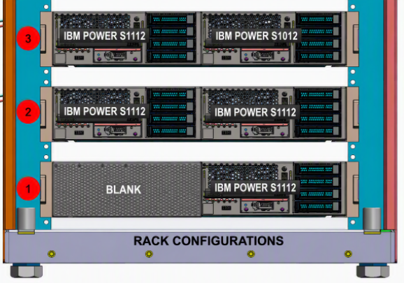
The Power S1112 supports three rack configuration layouts:
- Single system — one Power S1112 in the rack
- Side-by-side — two Power S1112 systems in the same rack
- Mixed — a single Power S1112 side-by-side with a single IBM POWER S1012 system (by convention the IBM POWER S1012 occupies the right bay, though placement is flexible)
Power and Cooling
Introduction
Power delivery and cooling rarely get the attention that processors and memory do, but they're just as much a part of what makes the IBM Power S1112 Power11 one-socket scale-out server an enterprise-grade machine. None of the silicon-level reliability covered elsewhere in this book means much if the system can't be kept powered and cool, year after year, without interruption.
Enterprise systems are expected to run continuously for years while carrying business-critical workloads. That kind of longevity depends on power and thermal management holding processor, memory, storage, and I/O components within their safe operating limits at all times — not just under typical load, but during the spikes too.
The Power S1112 power and cooling architecture is built around six related goals: continuous availability, energy efficiency, hardware protection, dynamic monitoring, predictive management, and datacenter optimization.
Importance of Power and Cooling Design
At its core, a server is a machine that turns electrical energy into computing capability — and, as a byproduct, into heat. That conversion happens every time the system does work:

Because that heat is unavoidable, every server design has to solve two problems at once: deliver stable power, and remove the heat that power generates, efficiently enough that it never threatens the hardware.
Power Subsystem overview
The Power S1112 power subsystem is responsible for delivering electrical power to every internal component — the Power11 processor, memory modules, PCIe adapters, storage devices, fans, and system management components. Power flows from the external source through the power supply units, into power distribution, and out to each component group:

Power Supply Units (PSU)
Power supplies do the unglamorous but essential work of converting incoming datacenter power into the specific voltages every component actually needs. Beyond simple conversion, they also handle voltage conversion, power regulation, fault detection, and component protection. In practice, that looks like a straightforward chain from wall power to working hardware:

Redundant Power Design
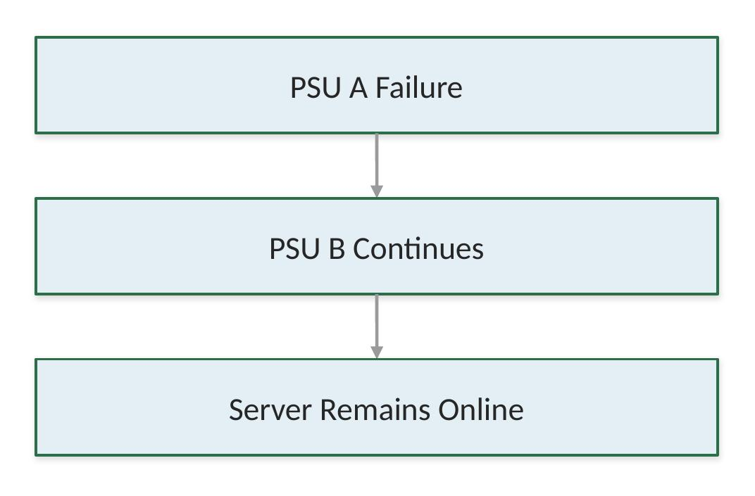
Enterprise systems can't afford to depend on a single power component — a single point of failure anywhere in the power path is a single point of failure for the whole server. Without redundancy, one power supply feeds the Power S1112, and if it fails, the server goes down with it:

With redundancy, the same server is fed by two independent supplies instead of one:

The practical benefit shows up exactly when it matters — at the moment of failure:
Dual Power Source Architecture
Redundant power supplies only fully protect you if they're also wired to separate electrical feeds. Two power supplies plugged into the same circuit still share a single point of failure — just one level further upstream.

That separation delivers protection from circuit failures, maintenance flexibility, and improved uptime.
Power Monitoring
Modern Power systems don't wait for something to go wrong before checking on it — power conditions are monitored continuously, including voltage levels, power supply health, power consumption, and environmental conditions. That monitoring follows a consistent path from the hardware itself up to the people responsible for acting on it:

Dynamic Power management
Power draw isn't static — it tracks whatever the system is actually being asked to do. A server idling overnight pulls meaningfully less power than the same server during a demanding processing window:

Letting power draw flex with workload improves efficiency, reduces unnecessary consumption, and controls heat generation.
Energy Efficiency Considerations
Energy efficiency matters because the electricity bill for running a server is never just about the server. Datacenter costs stack three layers on top of each other — server electricity, cooling electricity, and facility infrastructure:

A more efficient server doesn't just save on its own power draw — it reduces the cooling load too, which compounds into meaningfully lower long-term operating cost.
Cooling System overview
The cooling subsystem exists to remove the heat produced by every major hardware component — processor, memory, PCIe adapters, and storage devices. That heat has to move somewhere, and the cooling system gives it a defined path out of the chassis:

Front-to-Rear Airflow Design
Rack servers, the Power S1112 included, are built around front-to-back airflow — the standard convention in modern datacenters. Cool air is drawn in from the cold aisle at the front of the rack, passes across the processor, memory, and adapters, and exits as heated exhaust into the hot aisle at the rear.

Because this matches how most datacenters are already laid out, the server's airflow design works with the room's airflow design rather than against it.
Cooling Fan Architecture
System fans are responsible for keeping air actually moving through the chassis. Under normal conditions, fans hold a steady, efficient speed. Once temperature starts climbing, sensors pick that up and fan speed increases in response, before the situation becomes a problem:

Thermal Sensors
The Power S1112 places monitoring points throughout the hardware rather than relying on a single temperature reading. Sensors track processor temperature, memory temperature, internal airflow, and power components. Each reading flows through the same chain — from the sensor itself, to the service processor, through firmware analysis, and out as a cooling adjustment:

Thermal Protection
If temperature moves outside expected limits, the response happens in three steps: Temperature Increase → Cooling Response → System Protection Actions. The objective behind all three is simple: protect hardware before damage occurs.

Relationship between Workload and Cooling
Different workloads put very different demands on the cooling system, because they generate very different amounts of heat:

Workloads that tend to run heavy include analytics, databases, AI processing, and large batch jobs — the kind of sustained, CPU-intensive work that keeps utilization high for extended periods.
Datacenter Cooling Planning
A Power S1112 installation needs cooling planning that goes beyond the server itself. For rack cooling capacity, the relevant questions are whether the rack can actually remove the heat the configuration will generate, and whether airflow paths are genuinely clear. For room cooling, the relevant factors are air conditioning capacity, air distribution through the space, and whether hot/cold aisle separation is maintained in practice. For equipment placement, poor placement creates a problem that compounds — blocked airflow leads to heat build-up and directly to hardware stress:

Power and Cooling High Availability
Real availability planning doesn't stop at the server's edge. A resilient design connects the server to two independent power grids and backs it with two independent cooling systems, so that no single upstream failure can take the system down:

Environmental Monitoring
Datacenter teams keep an eye on more than just the server itself — temperature, humidity, airflow, and power consumption are all tracked. That monitoring follows the same general pattern seen throughout this section:

Best Practices for Power and Cooling
A handful of operational habits make the difference between a power and cooling design that works on paper and one that holds up in production:
- Use redundant power supplies
- Connect power supplies to separate feeds
- Maintain proper airflow
- Keep front and rear areas clear
- Monitor environmental conditions
- Avoid overloaded racks
- Maintain clean cable routing
- Plan capacity before adding servers
- Review power growth requirements
Common Power and Cooling Issues
Blocked airflow is usually caused by poor cabling or an incorrect rack layout. The impact is straightforward: increased temperature, with everything downstream of that.
Overloaded power circuit is typically the result of connecting too many devices to a single circuit. The risk here is availability — an overloaded circuit is more likely to trip or fail under load.
Insufficient cooling is often the product of high-density deployment without matching cooling planning. The consequence is ongoing component stress, which shortens hardware lifespan even when it doesn't cause an immediate outage.
Summary
The IBM Power S1112 power and cooling architecture supports enterprise-class availability by combining reliable power delivery, redundant power design, continuous monitoring, dynamic power optimization, efficient airflow management, intelligent cooling control, and tight integration with datacenter infrastructure. Proper power and thermal planning — at the server level and the datacenter level — is what lets the Power11 platform run reliably under mission-critical workloads for years rather than months.
Reliability, Availability, and Serviceability (RAS)
Reliability, Availability, and Serviceability — RAS for short — isn't a marketing checkbox on IBM Power systems. It's the design philosophy that runs through every layer of the IBM Power S1112 Power11 one-socket scale-out server, from the silicon up to the management console.
Performance gets a system noticed, but it's RAS that decides whether a business can actually trust that system with something that matters. Enterprise workloads don't just need to run fast — they need to keep running, correctly, under the kind of conditions that would quietly corrupt data or silently drop transactions on a less carefully engineered platform.
That distinction matters most in environments where downtime has a real, immediate cost: banking systems, healthcare platforms, manufacturing systems, ERP applications, financial reporting, and government services. These environments need infrastructure deliberately engineered to minimise downtime and protect data integrity — not infrastructure that merely tries to recover gracefully after something has already gone wrong.
IBM builds RAS into every layer of the stack — processor, memory, firmware, hypervisor, storage, I/O subsystem, and management layer.
What this looks like in practice: IBM's published RAS figures for the Power11 family describe the platform as designed to deliver 99.9999% uptime, with zero planned downtime for routine system maintenance, enabled by autonomous patching and live updates. That specific figure is calculated for a single E1180 enterprise system, the largest in the family, so it shouldn't be read as a guaranteed number for the S1112 — but it's a useful indicator of the engineering standard to which the whole Power11 architecture is held, scaled-down implementation included. The S1112 inherits the same RAS design philosophy described throughout this section, even though its smaller, single-socket footprint means some of the highest-end redundancy options available on enterprise-class systems don't apply.
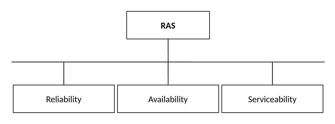
Understanding RAS
RAS consists of three related but distinct concepts. Each branch addresses a different operational question: how often something goes wrong, what happens to the application when it does, and how quickly it can be fixed.
Reliability
The ability of a system to operate correctly without failures.
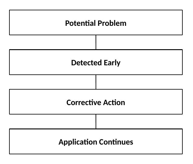
The goal here isn't recovery — it's prevention. A reliable system catches problems before they ever get the chance to touch an application. That shows up as detecting hardware errors, correcting temporary faults, monitoring component health, and protecting data integrity. The underlying pattern repeats throughout this section:
Availability
Keeping applications running when failures occur.
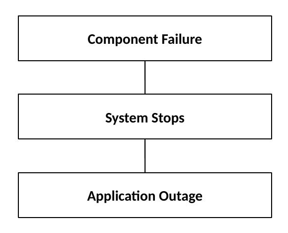
No system, however well built, eliminates failures — components do eventually fail. What separates an enterprise design from a conventional one is what happens the moment a failure occurs. On a system without redundancy, that moment is unforgiving:
The Power design goal is to interrupt that chain before it ever reaches the application:
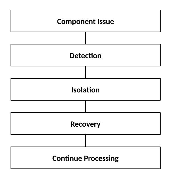
The difference between those two diagrams is, in a real sense, the entire business case for RAS engineering.
Serviceability
The ability to identify and repair problems quickly.
Reliability and availability minimize how often and how visibly things go wrong. Serviceability is about what happens next — when a component genuinely needs attention, how quickly can it be found, understood, and fixed? The goals are faster problem identification, accurate diagnostics, reduced repair time, and minimal business impact. In practice, that's a five-step process:
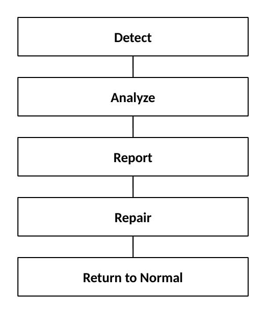
IBM Power RAS Design Philosophy
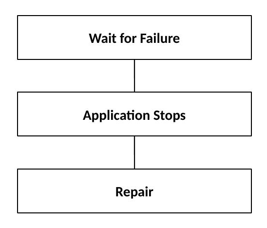
Most traditional server designs are reactive almost by default:
IBM Power systems are built around a fundamentally different premise — catch the problem before it becomes an outage at all:
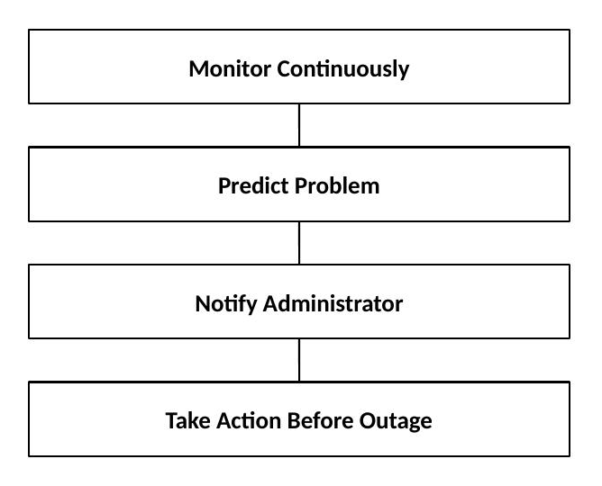
That's the single idea underneath nearly every RAS feature described in the rest of this section: prevention first, automatic recovery second, and manual intervention only as a last resort.
Processor Reliability Features
The Power11 processor includes hardware reliability technology built directly into the silicon, not bolted on afterward. Several internal areas are continuously monitored: execution units, cache structures, internal communication paths, and processor logic.
Worth knowing: Power11 processors also support a degree of self-healing at the core level — spare processor cores can be automatically substituted when a predictive error is detected on a chip, without requiring any customer or service action. The spare is scoped to that specific processor chip, so it doesn't introduce a memory-affinity penalty elsewhere in the system. This kind of automatic, invisible mitigation is a good example of what "prevention first" actually looks like in hardware.
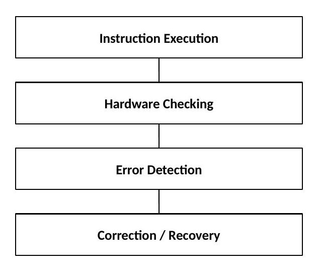
Processor Error Detection
The processor continuously checks its own operations as they happen, rather than trusting that everything executed correctly and finding out otherwise later:
Processor Recovery
Not every processor error is a sign of a failing component — many are transient, caused by electrical disturbances or transient hardware conditions. For these temporary conditions, the processor can recover in place without any visible interruption:
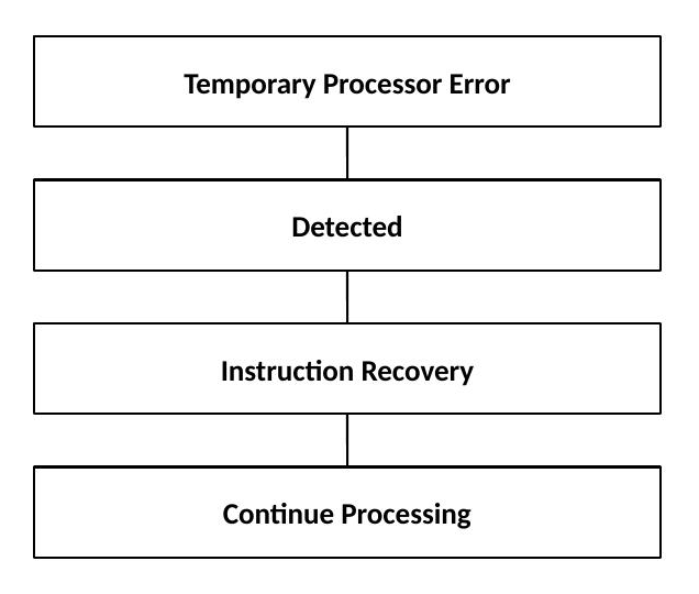
That kind of silent, automatic recovery is a meaningful contributor to real-world application uptime. The kind of event that might have caused a crash on a less capable system never even registers as an incident here.
Cache Protection
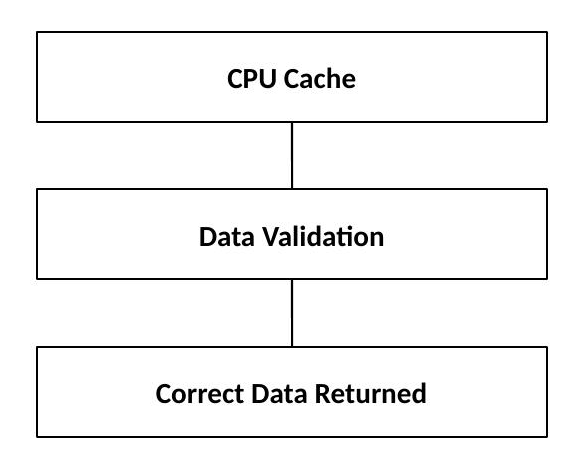
Processor cache holds active application data, which makes it a particularly sensitive area — a corrupted cache line can silently produce an incorrect result rather than an obvious crash. Cache reliability covers error detection, correction mechanisms, and fault handling:
Memory Protection Architecture
Memory reliability is one of the strongest areas of the entire IBM Power design, and for good reason — memory errors are some of the most dangerous failures a system can experience, precisely because they don't always announce themselves. They can manifest as application crashes, incorrect calculations, or database corruption. Power systems are built specifically to guard against all three.
ECC Memory Protection
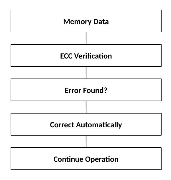
Error Checking and Correction (ECC) detects and corrects memory problems automatically, as part of the normal read path rather than as a separate maintenance step:
Chipkill Memory Technology
Chipkill extends standard ECC protection by a meaningful step. Where conventional ECC handles individual bit errors well, Chipkill is specifically designed to survive the failure of an entire memory chip — a more severe event that standard ECC alone wouldn't reliably catch:
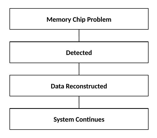
Chipkill provides protection from memory device failures rather than just bit-level errors, which increases availability and reduces downtime risk.
Predictive Failure Analysis
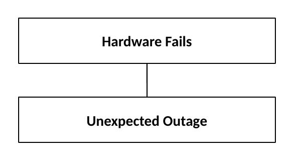
Predictive Failure Analysis (PFA) continuously monitors hardware behaviour, looking for early warning signs that precede failure rather than waiting for the failure itself. Without it, hardware failure is, by definition, a surprise:
PFA replaces that surprise with a planned event:
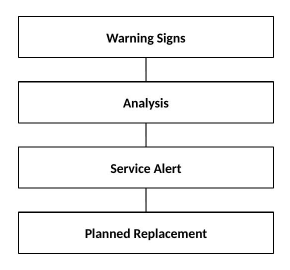
Components commonly monitored this way include memory errors, power components, cooling components, and storage devices.
First Failure Data Capture (FFDC)
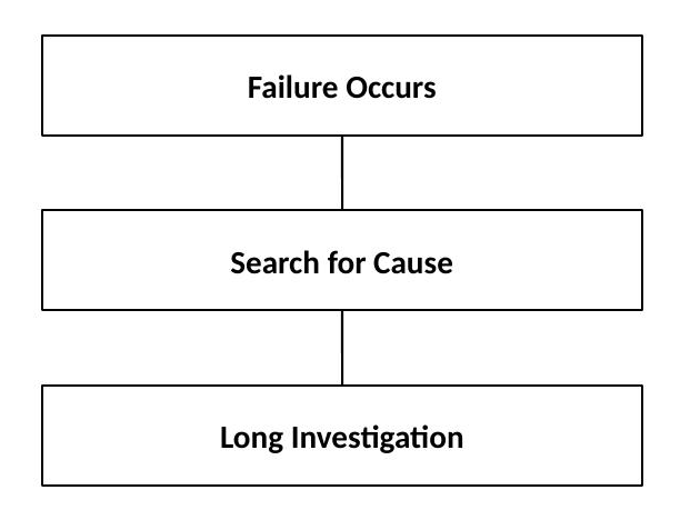
First Failure Data Capture is one of IBM's signature serviceability features, and it solves a problem every experienced systems administrator has run into: intermittent failures that are nearly impossible to reproduce on demand. Without FFDC, troubleshooting turns into open-ended detective work:
FFDC short-circuits that entirely by capturing diagnostic data automatically, at the exact moment the problem occurs:
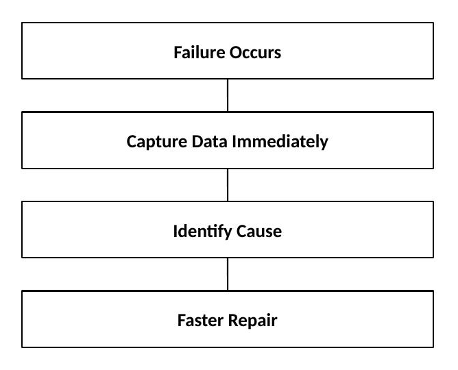
This changes the whole economics of troubleshooting — faster diagnosis, reduced downtime, and better support analysis, since IBM support is working from real data rather than a secondhand description of symptoms.
Service Processor Functions
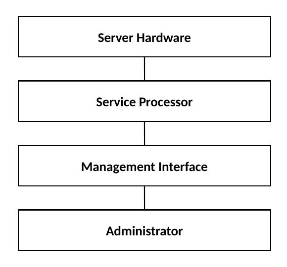
The service processor is a genuinely separate piece of hardware, running independently of the main system processor — which matters because it means hardware monitoring continues even if the main processor is degraded or unresponsive. Its responsibilities include hardware monitoring, error logging, system initialization, environmental monitoring, and service communication:
Firmware Reliability
System firmware manages low-level hardware operations, and its own reliability underpins everything running above it. Firmware handles hardware initialization, resource management, error handling, and recovery actions, working in close coordination with PowerVM, operating systems, and the service processor.
PowerVM Availability Features
Virtualization itself contributes meaningfully to availability. PowerVM sits between the physical hardware and every operating environment running on it:
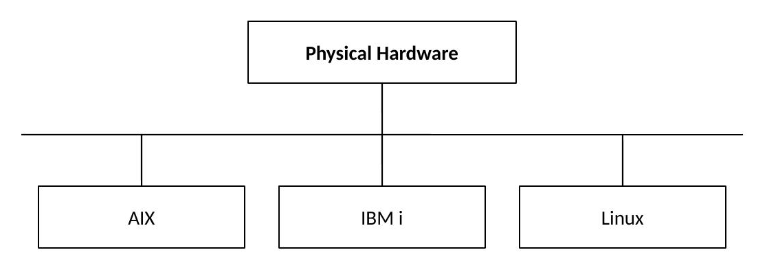
That layer provides workload isolation, resource control, and hardware abstraction. The practical payoff is straightforward: a problem in one partition does not necessarily affect the others sharing the same physical system.
Logical Partition Isolation
LPAR isolation is what makes partition-level protection real rather than aspirational — each partition operates behind a genuine boundary:
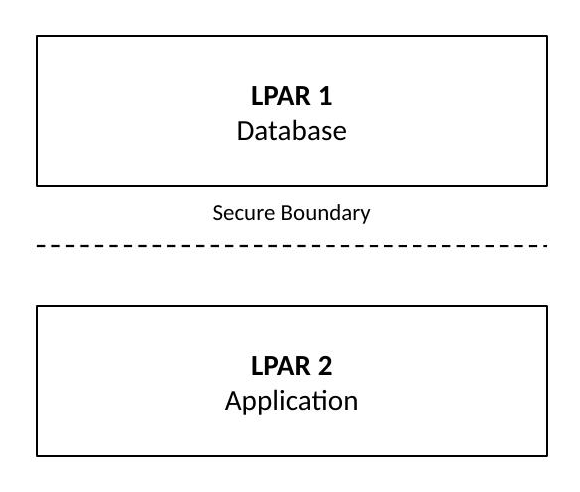
That boundary delivers security, stability, and controlled resource usage.
I/O Reliability
I/O paths are protected through redundancy. A single, unprotected path is fragile — any failure along it interrupts the whole connection:
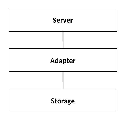
Enterprise designs route around that risk with two independent paths to the same destination:
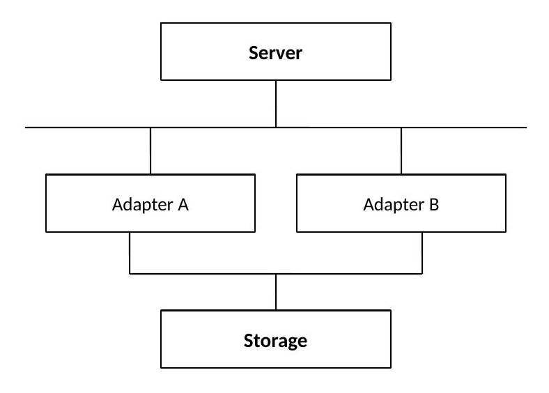
If Adapter A fails, Adapter B continues carrying the traffic — the application layer never sees an interruption.
Power Reliability
Power subsystem reliability follows the identical redundancy pattern applied to electrical supply:
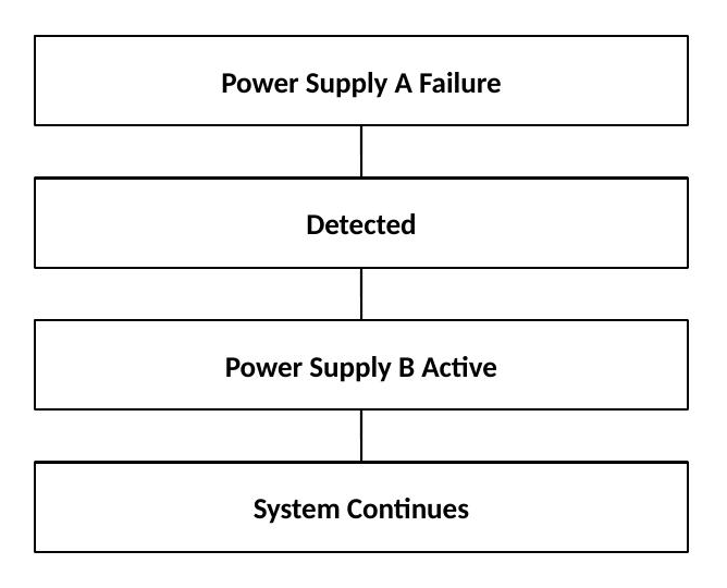
Cooling Reliability
Cooling failures are easy to overlook in a reliability discussion, but an overheating system can permanently damage components — making cooling redundancy just as important as power or I/O redundancy. Power's cooling design includes multiple fans, temperature sensors, and automatic adjustments:
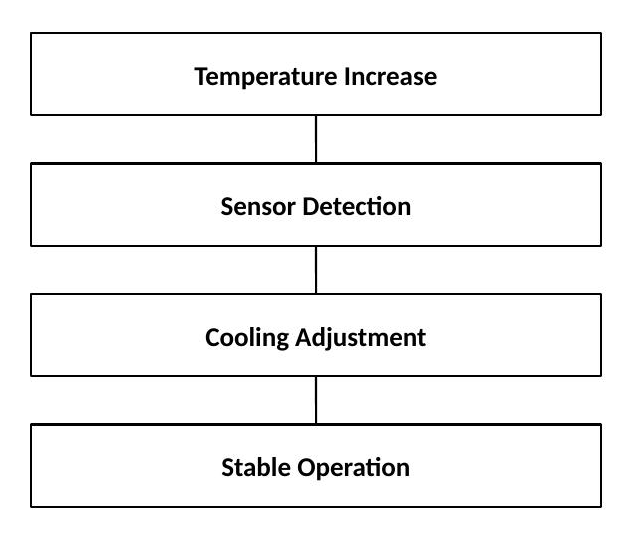
Maintenance and Service strategy
Power systems support efficient maintenance through clear diagnostics, error reporting, component identification, and guided repair. The goal that ties all of that together is a single metric: Minimum Time To Repair (MTTR). Every serviceability feature — FFDC, guided diagnostics, clear component identification — exists to drive that number down, because a lower MTTR translates directly into higher availability.
High Availability Design Approach
No single RAS feature, on its own, delivers high availability. It's the combination that does the work:
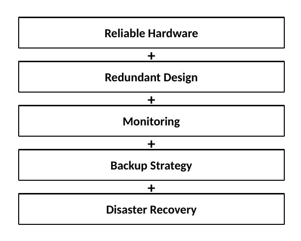
RAS hardware capability is necessary, but it only pays off fully when paired with operational processes — monitoring discipline, tested backups, a real disaster recovery plan — that put it to use.
A quick worked example: picture a regional bank's overnight batch settlement job running on a Power S1112 LPAR. Partway through the run, a transient memory error occurs on one DIMM. ECC detects and corrects it automatically — the batch job never sees an error, and nothing is logged as customer-visible. A week later, the same DIMM starts showing a higher rate of correctable errors. Predictive Failure Analysis picks up that trend, raises a service alert, and the operations team schedules a DIMM replacement during the next planned maintenance window — calmly, in daylight, with no application impact at all. That's the entire RAS philosophy in miniature: the first event was invisible because reliability worked, and the second was uneventful because serviceability gave the team time to act before reliability alone would have been enough.
RAS Best Practices
RAS still depends on the team operating the system staying disciplined about a few recurring habits:
- Monitor hardware events regularly
- Keep firmware current
- Configure redundant I/O paths
- Use redundant power sources
- Review service alerts
- Test recovery procedures
- Maintain documentation
- Plan maintenance windows
Every item on that list maps directly back to a feature described earlier in this section — redundant I/O paths only protect you if they're actually configured; service alerts only help if someone reviews them; PFA's early warning is wasted if nobody acts on it.
RAS Feature Quick Reference
Comparison with Other Power11 Systems
The IBM Power11 family isn't a single product — it's a range of systems built to cover everything from a single department's application server to a bank's entire core banking estate. That range exists because organizations genuinely differ: in how big their workloads are, how much downtime they can tolerate, how fast they expect to grow, and what they're willing to spend to get there.
The IBM Power S1112 sits at the compact end of that range. It's a one-socket scale-out server, and its whole reason for existing is to bring real Power11 capability into a footprint that smaller deployments can actually justify. Where the larger Power11 systems are chasing maximum scalability and consolidation, the S1112 is aimed at entry-level enterprise workloads, a smaller infrastructure footprint, cost-effective modernization off older Power hardware, branch and departmental environments, and a scale-out deployment model that grows by adding systems rather than enlarging one.
None of that makes it a lesser system — it makes it a different tool for a different job. Choosing between the S1112 and its larger siblings comes down to understanding what actually separates them, which this section walks through.
IBM Power11 Server Family Positioning
The Power11 lineup is best pictured as a ladder, with each rung built for a different scale of problem:

Each rung serves a genuinely different kind of business need. The table below lines up the named models so the positioning isn't just abstract. Figures are drawn from IBM's published data sheets at the time of writing and should be reconfirmed for the exact configuration being quoted, since IBM periodically refreshes processor and memory options within a model line.
* The S1112 is the newest, smallest entry in the Power11 lineup. Its exact core and memory maximums depend on the configuration ordered — always confirm against the current IBM data sheet rather than assuming parity with the S1122/S1124 figures above.
Scale-Up vs Scale-out Systems
The single biggest difference between Power11 systems isn't raw speed — it's how each one is meant to grow.
Scale-Up Architecture
Scale-up means increasing capacity within a single large system. You don't add boxes; you add resources to the box you already have:

That model is built for maximum consolidation onto a single platform, support for very large and demanding workloads, large shared resource pools, and enterprise datacenter deployments.
Scale-Out Architecture
Scale-out takes the opposite approach: when you need more capacity, you add another server rather than enlarging the one you have.

That model favors smaller and more digestible building blocks, easier incremental growth, naturally distributed workloads, and more flexible deployment patterns overall.
Power S1112 Positioning
The S1112 is built for organizations that want genuine IBM Power reliability, current Power11 processor technology, a lower entry point than the rest of the family, a compact deployment footprint, and full PowerVM virtualization capability. In practice, that tends to mean small and medium enterprises, branch offices, dedicated application servers, IBM i modernization projects, AIX workloads, and Linux applications.
Processor Scalability Comparison
Processor scalability is really just a proxy for one question: how much compute capacity can the platform absorb before you've outgrown it?
Single Socket Advantages
The S1112's one-socket architecture isn't a limitation that happened to it — it's a deliberate choice, and it pays off in concrete ways.
Lower Complexity
The architecture is about as simple as enterprise Power gets:

That simplicity shows up as easier day-to-day administration, more predictable performance, and simplified sizing, since there's no cross-socket math to do.
Reduced Latency
In multi-processor systems, the processors have to coordinate constantly:

In a single-socket system, that coordination overhead isn't there:

The communication paths are shorter and simpler, which is exactly why latency-sensitive workloads tend to behave more predictably on a single-socket platform.
Memory Scalability Differences
Different Power11 systems are sized for very different memory profiles, and matching the workload to the right tier matters more than it might seem. Smaller environments — a typical department application stack — run comfortably on scale-out systems:
Much larger environments need correspondingly larger memory pools:
These usually call for a larger Power system rather than a scale-out one.
I/O Expansion Differences
I/O requirements vary just as much as memory requirements, and the two families are intentionally tuned differently. The Power S1112 is focused on essential enterprise connectivity — network adapters, storage adapters, and compact expansion options. Larger systems are focused on significantly more adapter capacity, broader external connectivity, and larger-scale consolidation.
Workload Placement Comparison
The Power S1112 is well matched to IBM i workloads (business applications, ERP solutions, department systems) where integrated database performance, strong reliability, and lower operational complexity are priorities. For AIX, it handles application servers, middleware, and databases with enterprise UNIX reliability and full PowerVM virtualization. For Linux, it supports open-source applications, containers, and AI-enabled applications with Power architecture performance.
Larger Power11 systems earn their keep on a different category of problem — very large databases, hundreds of virtual machines on one platform, massive transaction workloads, and enterprise-wide consolidation projects. A large bank's core environment is a good illustration of what that actually looks like:

Virtualization Comparison
PowerVM runs across the entire Power11 family, which is one of the family's real strengths — the virtualization experience doesn't change as you move up the lineup, only the scale does. On a Power S1112:

On a larger enterprise system, the same PowerVM foundation supports a lot more on top of it:

The underlying technology is identical. The difference is purely one of scale.
Cost and Performance Balance
Every platform decision eventually comes down to the same balancing act:

No single system wins on all four dimensions simultaneously — the right platform is the one that balances them correctly for the workload and the budget in front of you.
When to Choose Power S1112
The Power S1112 is the right call when a compact Power11 system is what the environment calls for, workloads comfortably fit within one-socket capacity, cost efficiency genuinely matters, modernization off an older Power server is the driver, branch or departmental deployment is the use case, or a scale-out growth strategy fits how the business actually expands.
When to Choose Larger Power11 Systems
A larger system is the better fit when very large databases are already part of the picture, many workloads need to be consolidated onto one platform together, maximum memory capacity is a hard requirement, substantially more expansion capacity is needed than a compact chassis can offer, or the environment demands the highest tier of availability architecture.
Migration Considerations
Organisations moving off older Power systems should consider current processor usage, actual memory consumption, real storage requirements, and realistic growth forecasts. On the application side, the relevant questions are operating system version support, middleware platform constraints, database certification levels, and any vendor-specific requirements. Pulling those threads together usually looks like this:

A quick worked example: a mid-sized insurer running a Power8 system nearing the end of its service life is a common starting point for this conversation. Current utilisation shows the existing box is barely half-loaded outside month-end batch runs, the IBM i application stack is fully supported on current OS levels, and the growth forecast is modest — maybe 15% over three years. That profile points toward the Power S1112: it's a straightforward like-for-like modernization, not a consolidation project, and there's no indication the workload will outgrow a single socket any time soon. If that same insurer were instead consolidating four regional offices' Power8 systems onto one platform, with combined utilisation already pushing the ceiling of a single socket, the same exercise would point toward an S1124 or larger — the workload profile, not brand loyalty to either tier, should drive the decision.
Consolidation strategy
The S1112 isn't just for new, small deployments — it's also a credible consolidation target for organisations running several ageing, underutilised servers. Before:

After:

That consolidation typically delivers a meaningfully lower hardware footprint, simplified day-to-day operations, and better overall resource utilization.
Decision Matrix
Summary
The IBM Power S1112 strikes a deliberate balance between genuine enterprise capability and efficient scale-out deployment. It isn't a scaled-down compromise — it's a purpose-built entry point into the same Power11 technology that runs the largest systems in the family. The key differences worth remembering are a smaller footprint, an optimized one-socket architecture, lower day-to-day complexity, full PowerVM virtualization capability, and a strong fit for IBM i, AIX, and Linux workloads.
The Power S1112 is the right choice when an organisation wants the reliability of IBM Power11 technology without incurring the size, cost, or operational complexity of larger enterprise platforms. When the workload genuinely outgrows that footprint, the rest of the Power11 family — from the S1122 up through the E1180 — is built to take over without changing the underlying technology stack or the virtualization model the team already knows.
Architectural Trade-offs: IBM Power S1112 Scale-out vs Larger Power Systems
Introduction
There is no such thing as a perfect server design — only the right design for whatever constraints you are working under. Every architecture trades what is technically possible against what the business actually needs.
The IBM Power S1112 Power11 one-socket scale-out server is a good example of that trade-off in action. It brings real enterprise Power capability — reliability, virtualization, OS flexibility — into a compact, affordable system. Understanding what it gives up to achieve that is what determines whether it is the right fit.
The design balances six factors at once: performance, scalability, cost, reliability, simplicity, and room to grow. Maximizing all six simultaneously is not possible. Improving one affects the others.
Understanding Architectural Trade-offs
A trade-off, put simply, is improving one thing by accepting a limitation somewhere else.

Pushing hard on any one corner of that triangle affects the other two. Chasing maximum scalability increases cost. Keeping a system small caps growth. Adding more components increases capacity but also increases management complexity. None of this is a flaw — it is how engineering works. The goal is selecting the combination that fits what the business needs now and over the next few years.
One-Socket Architecture Advantages
The S1112 is built around a single processor socket, and that one decision shapes almost everything else about how it behaves.
1. a Simpler System Architecture
With only one socket, there is no second processor to coordinate with. In a multi-socket system, the processors are constantly communicating with each other:
Every time one processor needs something that lives closer to the other, the interconnect is involved. It works, but it is one more link in the chain and one more place where behavior can become unpredictable under load. The single-socket model does not have that problem:
The processor communicates directly with its own memory and I/O. Nothing in between — simpler, more predictable performance and one fewer factor to consider when planning workloads.
2. Lower Latency Design
Latency is the time it takes data to reach where it is needed. In a multi-socket system, that path can be longer than expected:

If a thread is running on Processor A but its data resides in memory attached to Processor B, the request must cross the interconnect. Usually a small delay, but under heavy workloads it accumulates. A single-socket design does not have that hop.
3. Cost Efficiency
The S1112 delivers real enterprise Power technology at a cost that fits a smaller organization: lower upfront spend, a smaller footprint, less power and cooling, simpler administration.
That suits small businesses needing enterprise reliability without enterprise scale, individual departments inside a larger company, branch sites, and modernization projects moving off older Power hardware.
In practice, the S1112 sits at the entry point of the Power11 scale-out lineup — below the S1122 and S1124, and well below the scale-up E1150/E1180 class. Exact limits vary by configuration, so check the current IBM datasheet. Directionally, if a workload is sized for a department, branch, or modernization project rather than enterprise-wide consolidation, the S1112 is usually where to start.
Scale-Out Architecture Benefits
Scale-out is the opposite of one large server. The environment grows by adding right-sized systems as the need arises:

Flexible Expansion
The most practical benefit is that you are not paying for capacity that is not yet needed. A typical rollout starts small and grows only when the business requires it:

Capacity is purchased when it is actually required, not years in advance based on a forecast.
Workload Distribution
Scale-out also makes it straightforward to assign each application its own dedicated system instead of consolidating everything together:

That separation provides better isolation — a resource-intensive application cannot starve the others — plus easier maintenance and independent scaling per tier.
Failure Domain Reduction
Smaller systems also reduce the blast radius when a failure occurs. Consider one large, heavily consolidated server:

A major outage on that system takes down everything running on it — a significant amount of risk concentrated in one place. Distributing the same workload changes the picture:

A failure on Server 1 affects Application A only, not B or C. Failures remain contained rather than cascading.
Scale-Out Trade-offs
Scale-out resolves the consolidation-risk problem by introducing a different one: more systems to manage.
More Systems to Manage
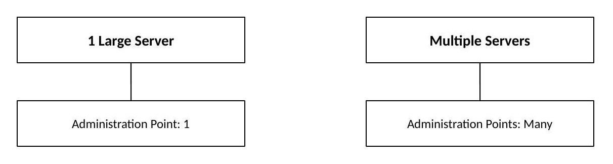
One large server has exactly one administration point. Distributing that workload across several smaller systems multiplies those points. That is a genuine operational cost that requires planning — centralized monitoring, automation, and processes that keep every system built and patched consistently.
Workload Movement Planning
If applications need to move between systems for maintenance, failover, or load balancing, that capability must be designed in from day one, typically through clustering, replication, and load balancing:

Scale-Up Architecture Advantages
Larger Power systems take the opposite approach — one system built to hold everything:

That approach offers its own advantages: heavy consolidation onto a single platform, headroom for demanding workloads, one system image, and large resource pools that can be partitioned as needed.
Scale-Up Trade-offs
The trade-offs run the other way as well — a meaningfully higher price, a larger footprint for power and cooling, more complex capacity planning, and a larger failure domain since more workload rides on one system.
Performance vs Cost Balance
Most architecture decisions come down to where the environment lands on this spectrum:

The S1112 sits deliberately in the middle rather than at either extreme — strong enough performance, a proportionate price, and enough operational simplicity that a dedicated specialist team is not required to run it.
Quick comparison (a planning lens, not a spec sheet — confirm exact figures against current IBM documentation):
Expansion Considerations
A one-socket design eventually reaches a ceiling — the cost of the simplicity it provides. The real question is not whether that ceiling exists. It is whether this workload will ever reach it.
Processor Growth — will demand outgrow what a single socket can comfortably handle over the planning horizon?
Memory Growth — will a database or in-memory workload outgrow a single-socket memory ceiling?
I/O Growth — will the environment eventually need more adapters or storage connectivity than a compact chassis supports?
There is no universal answer — it depends on the workload. Asking these questions up front, rather than discovering the limits two years into a deployment, separates a sound architecture decision from a fortunate guess.
Workload Suitability
Excellent Fit
- IBM i: ERP, accounting, inventory, manufacturing
- AIX: middleware, databases, business applications
- Linux: application services, containers, open-source solutions
A worked example: a regional distributor running IBM i ERP for approximately 150 users, plus a handful of Linux containers for integration and reporting, represents a straightforward S1112 use case. Modest requirements, with a real case for PowerVM-grade reliability without paying for unused capacity. If that same distributor later consolidates five regional offices onto one shared system, the conversation shifts toward scale-up — not because the S1112 became less capable, but because the workload changed.
Workloads That May Need Larger Systems
Some workloads are a better fit for a larger platform from day one: extremely large databases, very high transaction volumes, large-scale consolidation projects, hundreds of partitions, or anything with maximum expansion requirements defined from the start.
Virtualization Trade-offs
PowerVM enables one physical S1112 to host several operating environments side by side:

That delivers better hardware utilization and fewer physical systems to manage. However, shared resources are still shared — running several environments well on one system requires real capacity planning, ongoing monitoring, and clear governance over how changes are approved.
Hybrid Cloud Considerations
Most environments blend on-premises and cloud, tied together by automation:

The S1112 fits comfortably into that setup — it supports AIX, IBM i, and Linux, runs fully virtualized workloads through PowerVM, and integrates with automation and orchestration tooling.
Security Trade-offs
Moving to smaller, distributed systems changes the security picture. Workloads are separated by default, so an incident has a smaller blast radius. However, more systems require securing, and patch management must scale across all of them.
Operational Considerations
Skills — does the team already know PowerVM, or is that a learning investment? Are AIX and IBM i skills available in-house, or will they need to be hired or trained?
Monitoring — system-level monitoring across every deployed unit, ongoing capacity tracking rather than a one-time sizing exercise, and a defined firmware lifecycle process.
Growth Planning — designing exactly for today's workload is a common mistake. A sound architecture accounts for more than immediate needs:

Decision Guidelines
IBM Power S1112 Deployment Considerations
Introduction
Getting the IBM Power S1112 Power11 one-socket scale-out server up and running takes thoughtful preparation across hardware, virtualization, operating systems, storage, networking, security, and ongoing management. A structured deployment approach ensures the system meets business requirements, delivers expected performance, maintains availability, supports future growth, and remains secure and manageable over time.
Deployment Lifecycle overview
A typical Power S1112 deployment follows sequential phases, each completed and validated before proceeding: Requirement Planning → Workload Assessment → Physical Installation → System Configuration → Validation → Production.
Requirement Planning
Before ordering or installing the system, understand the workload requirements.
Business Requirements
Identify what applications will run, how critical they are, what availability level is required, and what growth is expected.

Workload Assessment
Collect current usage data across all resource areas before sizing the system.
Capacity Planning Checklist
Rack Preparation
Physical installation begins with rack planning. Verify available rack space, rack compatibility, power availability, cooling capability, and service clearance before proceeding.
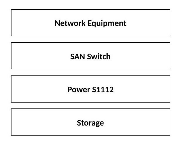
Power Planning
Production systems require reliable power. Plan power circuits, redundant feeds, UPS capacity, and power monitoring. The recommended design uses two independent power feeds to avoid a single power dependency:

Cooling Planning
Before installation, verify datacenter temperature, airflow direction, rack density, and cooling capacity. Incorrect cooling directly affects reliability.

Network Planning
Network architecture must be prepared before deployment. Use separate networks for production traffic (application traffic and user connectivity), management traffic (administration and monitoring), and backup traffic (backup operations and replication) to avoid contention and improve security.
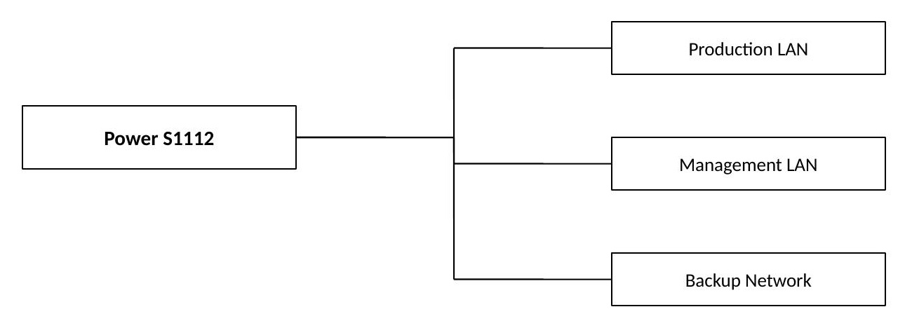
Storage Planning
Storage design decisions include internal storage (boot devices and local requirements) and external SAN storage for enterprise workloads. Plan storage capacity, performance, redundancy, and backup strategy before deployment.
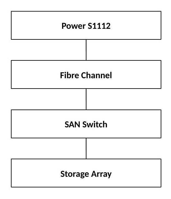
Virtualization Planning
IBM Power systems commonly use PowerVM. Planning areas include number of LPARs, CPU allocation, memory allocation, virtual networking, and virtual storage.
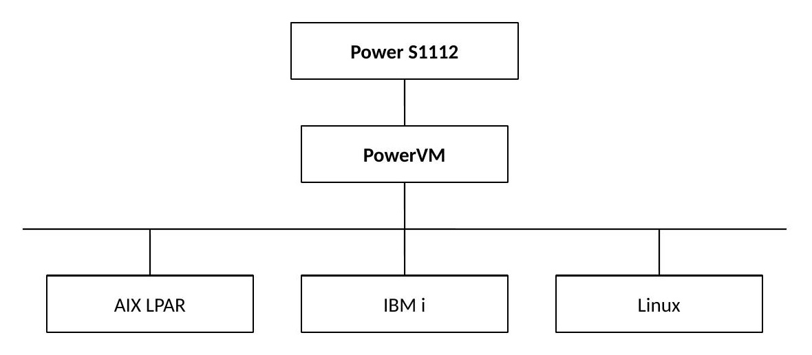
Logical Partition (LPAR) Design
A good LPAR design logically separates workloads, providing isolation, easier maintenance, and security control.

Processor Allocation Planning
Dedicated processors are best for critical databases and workloads requiring predictable performance. Shared processors are best for multiple workloads where higher overall utilization is the priority.
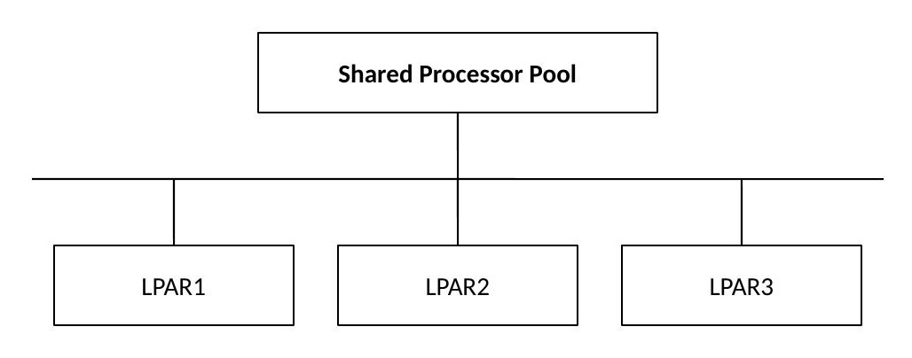
Memory Allocation Planning
Account for operating system requirements, database memory (critical), application requirements, and future expansion. Avoid overcommitting memory — performance degradation from excessive paging is the most common consequence:

Virtual I/O Server (VIOS) Planning
VIOS provides shared I/O services to LPARs. Plan for redundancy so a single VIOS failure doesn't affect every LPAR, and size adapter assignments and performance requirements before deployment.

Hardware management Console (HMC)
The HMC provides centralized management for system configuration, LPAR management, firmware operations, hardware monitoring, and service functions. Running a serious Power system without HMC is not recommended.

Firmware Lifecycle Planning
Firmware is a critical part of system reliability. Plan firmware levels, an update schedule, compatibility checks, and maintenance windows before deployment.
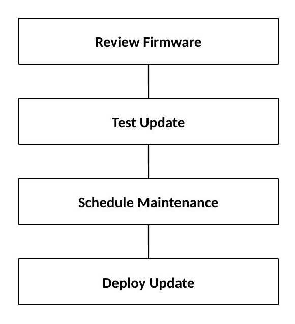
Operating System Planning
Supported environments require lifecycle management. For AIX, review version compatibility, application certification, and patch levels. For IBM i, review release level, application dependencies, and database requirements. For Linux, review distribution support, kernel levels, and the application stack.
Security configuration
Security must be included from the beginning. Plan access control (administrator accounts, role-based access, authentication), network security (firewall rules, network segmentation, encryption), and firmware and system security (trusted firmware levels, secure configurations, regular updates).
Monitoring Setup
After installation, configure monitoring for CPU, memory, storage, network, and hardware events. Track hardware events before they become outages.

Backup and Recovery Planning
Define recovery objectives before going to production. The Recovery Point Objective (RPO) defines how much data can be lost; the Recovery Time Objective (RTO) defines how quickly service must return. These two numbers drive the entire backup strategy.

Testing before Production
Perform full validation before going live: hardware health check, network connectivity test, storage path verification, LPAR startup testing, application testing, backup testing, and failover testing.
Production Readiness Checklist
Operational Best Practices
After deployment, maintain the system with these habits:
- Monitor capacity regularly
- Keep firmware updated
- Review security settings
- Maintain documentation
- Test recovery procedures
- Review growth requirements
- Automate routine operations
IBM Power S1112 Architecture overview
The IBM Power S1112 is a next-generation Power11 processor-based one-socket scale-out server, built to bring enterprise-class performance, security, reliability, and flexibility into a compact platform.
It carries forward the same philosophy that's defined Power systems for years — high throughput, workload consolidation, virtualization efficiency, and near-continuous availability — while also being built for what modern IT actually looks like today: hybrid cloud, AI workloads, automation, and a real focus on energy efficiency.
Think of the S1112 as an entry-to-mid-range enterprise system. It's a good fit for organizations that need mission-critical application hosting, database environments, business applications, hybrid cloud workloads, virtualized infrastructure, edge computing deployments, and AI-assisted enterprise processing.
Where commodity servers tend to chase raw clock speed, IBM Power systems are engineered around a different set of priorities — processor utilization, advanced simultaneous multithreading, memory bandwidth, reliability, secure workload isolation, and the kind of long operational lifecycle enterprises actually plan around.
Power11 System Architecture Foundation
The S1112 is built on the IBM Power11 processor architecture, and its major components break down into seven areas: the Power11 Processor Complex, Memory Subsystem, System I/O Fabric, Storage Subsystem, Virtualization Layer, System Management Components, and Reliability and Security Infrastructure.
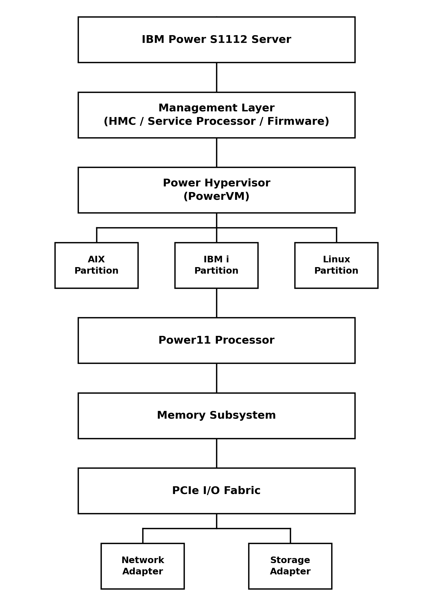
One-Socket Scale-out Design
The S1112 runs on a single processor socket — the physical processor package installed inside the server. That's a deliberate departure from how traditional enterprise systems usually scale, which is vertically: adding more sockets, pooling more shared memory, expanding the chassis.
The S1112 instead follows a scale-out model. Rather than one system growing larger and larger, individual servers each provide optimized compute capacity, and you add more of them as workload demand increases. The scale-up approach concentrates everything onto one very large server:

Scale-out spreads the same total workload across multiple right-sized systems:

That shift brings real, practical benefits: a lower initial investment, easier capacity expansion, a smaller datacenter footprint, better workload placement, and more flexibility in how you deploy things.
Processor-Centric Architecture
At the core of the S1112 sits the Power11 processor. It's not just a chip — it's a processor complex, integrating high-performance Power cores, large cache structures, memory controllers, security acceleration, reliability logic, and high-speed I/O connectivity all in one package.
That combination is what makes it well-suited to demanding enterprise work, particularly transaction throughput (banking transactions, ERP processing, order management systems), database processing (IBM Db2, Oracle, PostgreSQL, and enterprise analytics), and virtualized workloads (multiple AIX LPARs, IBM i environments, and Linux workloads running side by side on the same hardware).
Simultaneous Multithreading Architecture
One of the defining traits of IBM Power processors is advanced SMT — simultaneous multithreading — which lets a single processor core execute multiple software threads at once instead of working through them one at a time.
Without SMT, a core has to finish one thread before it can properly move to the next:

With SMT, several threads execute together on the same core:

The payoff is higher CPU utilization, better throughput, fewer idle processor cycles, and better workload consolidation overall.
Memory-Centric Design Philosophy
Enterprise performance isn't just about how fast the CPU runs — it's also about how quickly data actually reaches it. The S1112's memory architecture is built around high bandwidth, low latency access, error correction, and availability. On the reliability side, memory features include error detection, error correction, fault isolation, and predictive failure handling — capabilities that matter most in environments where downtime or data corruption simply isn't an option, like financial systems, healthcare applications, and manufacturing systems.
Integrated Virtualization Architecture
Virtualization sits at the core of the Power architecture, and the S1112 supports it through IBM PowerVM, which creates Logical Partitions (LPARs) on top of the shared physical hardware:

That setup gives you multiple operating systems running on one physical server, dynamic resource allocation, higher overall utilization, solid workload isolation, and simpler administration than managing separate physical boxes for each environment.
Operating Environment Support
The S1112 architecture supports three enterprise operating environments. IBM AIX is used for enterprise applications, databases, middleware, and transaction processing. IBM i is used for business applications, ERP workloads, and integrated database environments. Linux on Power is used for open-source applications, containers, AI workloads, and cloud-native environments.
Security Architecture overview
Security in the Power11 architecture isn't bolted on — it's built into the design, with secure system initialization, hardware-assisted security functions, firmware protection, workload isolation, and secure virtualization boundaries all working together. That protection runs through every layer of the stack, from the application down to the hardware itself:

Reliability by Design
The S1112 inherits IBM's enterprise RAS capabilities — Reliability, Availability, and Serviceability. The underlying goal is simple to state even if it's hard to engineer: detect, isolate, recover, and keep operating. That shows up in practice as processor error recovery, memory error correction, ongoing hardware monitoring, predictive failure alerts, and built-in service diagnostics.
Typical Power S1112 Deployment Architecture
Here's what a fairly typical enterprise deployment looks like end to end — from the users making requests all the way down to where the data actually lives:
