
Abstract
IBM® FlashSystem™ 720 and IBM FlashSystem 820 storage systems deliver high performance, efficiency, and reliability for shared enterprise storage environments, helping clients around the world address performance issues with their most important applications and infrastructure. These storage systems can either complement or replace traditional hard drive arrays in many applications, including online transaction processing (OLTP), business intelligence (BI), online analytical processing (OLAP), virtual desktop infrastructures, high-performance computing, and content delivery solutions (such as cloud storage and video on demand).
Contents
Table of contents
Introduction
IBM® FlashSystem™ 720 and IBM FlashSystem 820 storage systems deliver high performance, efficiency, and reliability for shared enterprise storage environments, helping clients around the world address performance issues with their most important applications and infrastructure. These storage systems can either complement or replace traditional hard drive arrays in many applications, including online transaction processing (OLTP), business intelligence (BI), online analytical processing (OLAP), virtual desktop infrastructures, high-performance computing, and content delivery solutions (such as cloud storage and video on demand).
As standard shared primary data storage devices, FlashSystem 720 and FlashSystem 820 storage systems deliver performance beyond that of most traditional arrays, even those that incorporate SSDs or other flash technology. These storage systems can also be used as the top tier of storage alongside traditional arrays in tiered storage architectures such as the IBM Easy Tier® functionality available in IBM System Storage® SAN Volume Controller or IBM Storwize® V7000 storage virtualization platforms.
Based on single level cell (SLC) flash, FlashSystem 720 is targeted to write-heavy enterprise workloads; enterprise multi level cell (eMLC) flash-based FlashSystem 820 is targeted to read-heavy workloads, where workload is distributed across multiple servers.
Figure 1 shows FlashSystem 720 and FlashSystem 820.

Figure 1. FlashSystem 720 and FlashSystem 820
Did you know?
IBM FlashSystem storage systems deliver over 500,000 read IOPS and up to 5 GBps bandwidth with less than 100 microseconds latency, while they provide up to 24 TB of total usable capacity or up to 20 TB of 2D Flash RAID protected data storage just in 1U of rack space.
FlashSystem 720 and FlashSystem 820 feature mission critical availability and reliability, and multiple layers of data correction, chip redundancy, and redundant hot swap components.
Key features
IBM FlashSystem storage systems deliver advanced performance, scalability, reliability, security, and energy-efficiency features. FlashSystem 720 and FlashSystem 820 storage systems are the appropriate choice for mission critical enterprise environments with the following characteristics: high storage performance requirements, such as low latency (microseconds as opposed to milliseconds), high bandwidth (gigabytes per second), or high IOPS (hundreds of thousands of I/O operations per second).Scalability and performance
The FlashSystem storage systems offer numerous features to boost performance and improve scalability:
- FlashSystem storage systems can provide more than 500,000 IOPS and up to 5 GBps bandwidth for storage I/O-intensive enterprise workloads.
- FlashSystem 820 can scale up to 24 TB of storage capacity, while FlashSystem 720 supports up to 12 TB.
- A single 42U rack containing 42 1U FlashSystem storage systems can provide up to 840 TB of protected storage with more than 20,000,000 IOPS and up to 210 GBps bandwidth.
- FlashSystem storage systems feature one of the industry's highest flash capacity density metric (usable GB per rack space) and performance density metrics (IOPS and bandwidth per rack space).
- FlashSystem storage systems support up to 1,024 logical volumes.
- FlashSystem storage systems offer choice of 8 Gb Fibre Channel or 40 Gb QDR InfiniBand connectivity to match the performance of most demanding I/O intensive applications.
Availability and serviceability
The FlashSystem storage systems provide many features to simplify serviceability and increase system uptime:
- FlashSystem storage systems use overprovisioning and advanced wear leveling techniques to dramatically improve write endurance of the flash modules to extend their lifetime.
- FlashSystem 720 and FlashSystem 820 offer multiple layers of data protection (ECC, Variable Strip RAID, and 2D Flash RAID) to prevent an unplanned outage in case of a flash chip or module failure.
- FlashSystem 720 and FlashSystem 820 support hot-swap flash modules which allows to replace the failed module without service interruption to eliminate planned downtime.
- FlashSystem storage systems offer two redundant hot-swap power supplies and eight dual-motor non-hot-swap redundant fans to provide cost-efficient availability for applications.
- Easy-to-read LCD display indicates system errors to lead the technician to failed (or failing) components. This panel simplifies servicing and speeds up problem resolution, helping improve system availability.
- Three N+1 redundant batteries help prevent data loss by backing up data in RAM buffers allowing them to be written to a flash module in case of power failure.
- Two built-in redundant management modules in an active-passive configuration continuously monitor system parameters, triggers alerts, and performs recovery actions in case of failure, to minimize downtime.
- One-year customer replaceable unit and on-site limited warranty, next business day 9x5. Optional service upgrades available.
Manageability and security
Powerful systems management features simplify local and remote management of the FlashSystem storage systems:
- FlashSystem storage systems have a built-in LCD display allowing to perform basic configuration, management, and monitoring tasks, simplifying administration.
- FlashSystem storage systems include a management module to monitor server availability and perform remote management.
- The management module provides extensive security features, including role-based user authentication and access control, LDAP support, and SSH protocol for secure remote systems management.
- LUN masking feature allows to control access to a logical volume from the host side to prevent unauthorized data access and modification.
Energy efficiency
The FlashSystem storage systems offer the following energy-efficiency features to save energy, reduce operational costs, increase energy availability, and contribute to a green environment:
- Energy-efficient flash components help lower operational costs.
- FlashSystem storage systems offer one of industry's best IOPS per watt ratio enabling greater energy savings.
- FlashSystem storage systems use hexagonal ventilation holes, a part of IBM Calibrated Vectored Cooling™ technology. Hexagonal holes can be grouped more densely than round holes, providing more efficient airflow through the system.
Locations of key components and connectors
Figure 2 shows the internal components of the FlashSystem unit.

Figure 2. Internal view of the FlashSystem unit
Figure 3 shows the rear of the FlashSystem unit with the Fibre Channel interfaces.
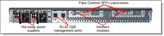
Figure 3. Rear view of the FlashSystem unit with the Fibre Channel interfaces
Figure 4 shows the rear of the FlashSystem unit with the InfiniBand interfaces.
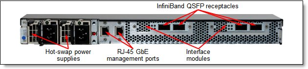
Figure 4. Rear view of the FlashSystem unit with the InfiniBand interfaces
Specifications
Table 1 lists the specifications.
Table 1. Specifications
| Specification | FlashSystem 720 | FlashSystem 820 |
| Form factor | 1U rack-mounted unit | |
| Flash module quantity | 12 (10+1+1) | |
| Flash module type | Single level cell (SLC) | Enterprise multi level cell (eMLC) |
| Flash module capacity | Single-density (SD): 500 GB Double-density (DD): 1 TB | Single-density (SD): 1 TB Double-density (DD): 2 TB |
| Maximum capacity | RAID 0 or JBOF: 6 TB (SD) or 12 TB (DD) RAID 5: 5 TB (SD) or 10 TB (DD) | RAID 0 or JBOF: 12 TB (SD) or 24 TB (DD) RAID 5: 10 TB (SD) or 20 TB (DD) |
| Flash module protection | Overprovisioning, wear leveling, CRC checksum, ECC, and module-level Variable Stripe RAID (standard); 2D Flash RAID (optional, pre-selected) | |
| RAID support | No RAID (JBOF mode); RAID 0 across flash modules; optional RAID 5 with hot spare across flash modules (2D Flash RAID) | |
| Host interfaces | 4x 8 Gb Fibre Channel (FC) or 4x 40 Gb QDR InfiniBand | |
| Read IOPS* | 525,000 | 525,000 |
| Write IOPS* | 400,000 | 280,000 |
| Read bandwidth** | 3.3 GBps (FC); 5 GBps (InfiniBand) | 3.3 GBps (FC); 5 GBps (InfiniBand) |
| Write bandwidth** | 3.3 GBps (FC); 4 GBps (InfiniBand) | 2.8 GBps (FC); 2.8 GBps (InfiniBand) |
| Read latency | 100 µs | 110 µs |
| Write latency | 25 µs | 25 µs |
| Systems management | LCD display with four control buttons; two management modules | |
| Cooling | Eight redundant non-hot-swap fans; each fan has two motors | |
| Power supply | Two redundant hot-swap 100 - 240 V ac auto-sensing power supplies | |
| Input power | 350 W | 300 W |
| Heat dissipation | 1194 BTU/hr | 1023 BTU/hr |
| Hot-swap parts | Flash modules, power supplies | |
| Security features | Role-based user security, SSH, LDAP, and LUN masking | |
| Platforms supported | IBM System x®, IBM Power Systems™, non-IBM x86 servers; Windows, Linux, IBM AIX®, VIOS operating systems | |
| Limited warranty | One-year on-site limited warranty with 9x5 next business day response | |
| Service and support | Optional warranty service upgrades and post-warranty services are available: on-site with 24x7 2-hour, 24x7 or 9x5 same day, or 9x5 next business day response | |
| Dimensions | Height: 44 mm (1.7 in.), width: 432 mm (17.0 in.), depth: 638 mm (25.1 in.) | |
| Weight | 12.7 kg (28 lb) | |
** 256 KB I/O block size.
Models
Table 2 lists the FlashSystem 720 and FlashSystem 820 models.
Table 2. Models
| Description | Machine type-model |
| IBM FlashSystem 720 | 9831-AS2 |
| IBM FlashSystem 820 | 9831-AE2 |
The FlashSystem 720 and FlashSystem 820 storage systems are shipped with the following items:
- Statement of Limited Warranty
- Quick start guide
- Documentation CD containing Installation and User's Guide
- Rail kit
- Two IEC 320-C13 to C14 rack PDU power cords
The FlashSystem 720 and FlashSystem 820 storage systems require interface and flash modules to be ordered with the base model. See "Interface modules" and "Flash modules" sections for details.
Interface modules
FlashSystem 720 and FlashSystem 820 support either 8 Gb Fibre Channel (FC) or 40 Gbps InfiniBand connectivity with the interface modules shown in Table 3 (only one feature can be selected).
Table 3. Supported interface modules
| Description | Feature code | Maximum quantity supported |
| 8 Gb FC 4 Port Ext Int | AF04 | 1 |
| IB QDR 4 Port Ext Int | AF05 | 1 |
Each interface module feature code contains two dual-port cards (either 8 Gb Fibre Channel or QDR InfiniBand) for a total of four ports in the system. FC interface modules come standard with four (one per each port) 8 Gb FC shortwave SFP+ transceivers with LC duplex connector. InfiniBand interface modules have QSFP receptacles.
FC interfaces support Fibre Channel Protocol (FCP) only, with point-to-point (FC-P2P), arbitrated loop (FC-AL), and switched fabric (FC-SW) topologies. FC interfaces can be configured as N_port or NL_port types. InfiniBand interfaces support SCSI RDMA Protocol (SRP) only. Dual-port interface modules support full active-active load balancing and failover multi-pathing, though host software support for this function can vary.
Flash modules
FlashSystem 720 and FlashSystem 820 provide configurable capacity and optional RAID 5 Protection feature with the flash modules listed in Table 4.
Table 4. Supported flash modules
| Description | Feature code | Maximum quantity supported |
| SLC flash module packs (for FlashSystem 720, only one pack can be ordered) | ||
| 6TB SLC RAID 0 (12-pack) | AF02 | 1 |
| 12TB SLC RAID 0 (12-pack) | AF03 | 1 |
| Base eMLC flash module packs (for FlashSystem 820, only one pack can be ordered) | ||
| 12TB eMLC RAID 0 (12-pack) | AF0E | 1 |
| 24TB eMLC RAID 0 (12-pack) | AF0F | 1 |
| RAID 5 protection (optional, pre-selected) | ||
| RAID 5 Protection | AF0K | 1 |
FlashSystem 720 flash modules use 32 nm SLC flash chips, nominally rated for 100,000 program/erase (P/E) cycles, and FlashSystem 820 flash modules use 32 nm eMLC flash chips, nominally rated for 30,000 P/E cycles.
FlashSystem 720 single-density flash module has a raw capacity of approximately 680 GB, and a usable capacity of approximately 500 GB after overprovisioning and Variable Stripe RAID overhead. FlashSystem 720 double-density flash module has a raw capacity of approximately 1.36 TB, and a usable capacity of approximately 1 TB after overprovisioning and Variable Stripe RAID overhead.
FlashSystem 820 single-density flash module has a raw capacity of approximately 1.36 TB, and a usable capacity of approximately 1 TB after overprovisioning and Variable Stripe RAID overhead. FlashSystem 820 double-density flash module has a raw capacity of approximately 2.72 TB, and a usable capacity of approximately 2 TB after overprovisioning and Variable Stripe RAID overhead.
Important: Flash module types cannot be mixed within a system.
The following flash module protection technologies are supported:
- Module-level Variable Stripe RAID
- Error correcting codes (ECC) to provide reconstruction of data from flash chips
- Checksums and data integrity fields protecting all internal data transfers within the system
- Overprovisioning to enhance write endurance and decrease write amplification
- Wear leveling algorithms that balance the number of writes among flash chips throughout the system
- Sweeper algorithms that ensure all data within the system is read periodically to avoid data fade issues
- Optional RAID 5 Protection feature with hot spare flash module to automatically rebuild data from the failing or failed module to restore a fully redundant state
In addition, FlashSystem 720 and FlashSystem 820 include three N+1 redundant batteries that are used to destage lookup tables and data from RAM buffers to the flash storage in case of power failure.
Three modes of operation are supported by the systems:
- RAID 0
- JBOF (just a bunch of flash)
- RAID 5 with hot spare (optional)
Definition: A combination of module-level Variable Stripe RAID and RAID 5 with hot spare across flash modules is called two-dimensional (2D) Flash RAID.
In a RAID 0 mode, data is striped across all available flash modules in a traditional RAID 0 layout (stripe size 4 KB).
JBOF mode allows each flash module to be treated separately without striping data across the modules. In JBOF mode, each flash module corresponds to a single logical volume.
In a RAID 5 mode, data is striped across 11 flash modules, with rotating parity protection in a 10+1 RAID 5 layout (stripe size 4 KB). In this mode, one module is reserved as a hot spare. Capacity available for user data is equivalent to the sum of usable capacities for 10 flash modules.
In a RAID 0 or RAID mode, yp to 1024 logical volumes (sometimes referred to as LUNs) can be created in the system, with a minimum size of 1 GB and a maximum size of the full available system capacity.
Unlike RAID 0 and JBOF mode, RAID 5 protection feature provides complete redundancy for the flash modules to avoid data loss in case of flash module failure. With RAID 5 feature activated, FlashSystem 720 and FlashSystem 820 offer full high availability and protection for mission critical data, without single point of failure.
Under the direction of the management module, the systems can coordinate data transfer between modules; for example, to rebuild a system-level RAID-5 data layout in case of a flash module failure, if RAID 5 Protection feature is activated.
Important: In RAID 0 or JBOF mode, failures of a single flash module containing data will most likely compromise system data integrity for logical volumes stored on those flash modules. If RAID 0 or JBOF mode is used, data must be replicated independently of FlashSystem 720 and FlashSystem 820 storage systems for protection against complete flash module failures.
Network cables
FlashSystem 720 and FlashSystem 820 support network cables that are listed in Table 5.
Table 5. Supported cables
| Description | Feature code | Maximum quantity supported |
| Fibre Channel cables (supported on Fibre Channel ports) | ||
| 1 m Fiber Cable (LC-LC) | 3700 | 4 |
| 5 m Fiber Cable (LC-LC) | 3701 | 4 |
| InfiniBand cables (supported on InfiniBand ports) | ||
| 1 m IBM QSFP Cop IB | A0RD | 4 |
| 3 m IBM QSFP Cop IB | A0RE | 4 |
| 3 m IBM QSFP Opt QDR IB | 5989 | 4 |
| 10 m IBM QSFP Opt QDR IB | 5990 | 4 |
| 1 m Mlnx QSFP Cop FDR14 IB | A2YG | 4 |
| 3 m Mlnx QSFP Cop FDR14 IB | A2YH | 4 |
| 3 m Mlnx QSFP Opt FDR14 IB | A2YL | 4 |
| 10 m Mlnx QSFP Opt FDR14 IB | A2YN | 4 |
Network management ports support 1000BASE-T connectivity and requires UTP Category 5, 5E, or 6 cable with RJ-45 connector (up to 100 meters).
Power cords
FlashSystem 720 and FlashSystem 820 come standard with two IEC 320-C13 to C14 rack PDU power cords. Optionally, country-specific line cords can be ordered if needed. See Table 6.
Table 6. Supported line cords
| Description | Feature code or part number | Maximum quantity supported |
| Line cord - 2.8m (China) | 6210 | 2 |
| Line cord - 2.8m (AS/NZ) | 6211 | 2 |
| Line cord - 2.8m (Europe) | 6212 | 2 |
| Line cord - 2.8m (Denmark) | 6213 | 2 |
| Line cord - 2.8m (S. Africa) | 6214 | 2 |
| Line cord - 2.8m (UK) | 6215 | 2 |
| Line cord - 2.8m (Swiss) | 6216 | 2 |
| Line cord - 2.8m (Ita/Chile) | 6217 | 2 |
| Line cord - 2.8m (Israel) | 6218 | 2 |
| Line cord - 2.8m (S Korea) | 6219 | 2 |
| Line cord - 2.8m (Argentina) | 6222 | 2 |
| Line cord - 2.8m (India) | 6269 | 2 |
| Line cord - 2.8m (Japan) | 6314 | 2 |
| Line cord - 2.8m 120V (US) | 6313 | 2 |
| Line cord - 2.8m (Taiwan) | 6386 | 2 |
| Line cord - 2.8m (Brazil) | 6532 | 2 |
Systems management
FlashSystem 720 and FlashSystem 820 have built-in LCD display (see Figure 5) to perform basic configuration and monitoring tasks.
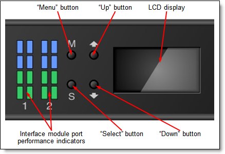
Figure 5. LCD display and controls
The following tasks can be performed through the LCD display:
- Configure IP addresses
- Reboot/shutdown the system
- Monitor system status
FlashSystem 720 and FlashSystem 820 are shipped with two management modules which run a highly customized Linux-based operating system that coordinates and monitors all significant functions in the system. Each management module has one RJ-45 Gigabit Ethernet port for remote management. Management modules are configured in an active/passive redundant pair. The following remote management methods are supported:
- Java-based graphical user interface (GUI) through web browser
- Command-line interface (CLI) through Telnet and Secure Shell (SSH)
- Simple network management protocol (SNMP)
The following tasks can be performed with the management module:
- Defining the user accounts and passwords
- Configuring email notifications
- Monitoring the status of the system:
- Event log
- Fans
- Temperatures
- Power
- Managing other FlashSystem units in the network from the single web console
- Controlling the FlashSystem unit:
- Powering on/off
- Uptading firmware
- Configuring network settings
- Changing storage mode (JBOF or RAID 0)
- Creating logical volumes (LUNs)
- Configuring LUN masking
- Configuring host interfaces
- Configuring user security
- Setting the date and time
Supported platforms
IBM FlashSystem systems support a wide range of operating systems (Windows Server 2003 and 2008, Linux, and IBM AIX®), hardware platforms (IBM System x®, IBM Power Systems, and x86 servers not from IBM), HBAs, and SAN fabrics. For specific information, see the System Storage Interoperation Center (SSIC): http://ibm.com/systems/support/storage/ssic
Physical and electrical specifications
FlashSystem 720 and FlashSystem 820 have the following physical, electrical, and environmental specifications:
- Dimensions and weight (approximate):
- Height: 44 mm (1.7 in.)
- Width: 432 mm (17.0 in)
- Depth: 638 mm (25.1 in)
- Weight: 12.7 kg (28 lb)
- Operating environment:
- Temperature:
- Operating: 10 - 35 degrees C (50 - 95 degrees F) at 30.5 m below to 3000 m above sea level (100 ft below to 9,840 ft above sea level)
- Non-operating: -10 - 50 degrees C (14 - 125 degrees F)
- Humidity:
- Operating: 20% - 80%
- Non-operating: 10% - 90%
- Supported electrical input:
- 100 - 240 (nominal) V ac; 50-60 Hz
- Input electrical power (approximately):
- FlashSystem 720: 350 watts
- FlashSystem 820: 300 watts
- BTU output:
- FlashSystem 720: 1194 BTU/hr
- FlashSystem 820: 1023 BTU/hr
- Acoustical:
- Noise emission: 8.0 bels
Warranty options
FlashSystem 720 and FlashSystem 820 have a 1-year on-site warranty with 9x5 next business day terms. IBM offers optional warranty and maintenance service upgrades for these systems:
- Warranty service upgrades
- 24x7 on-site repair with 2-hour target response time
- 24x7 on-site repair with same day target response time
- 9x5 on-site repair with same day target response time
- Maintenance (post-warranty) service offerings
- 24x7 on-site repair with 2-hour target response time
- 24x7 on-site repair with same day target response time
- 9x5 on-site repair with same day target response time
- 9x5 on-site repair with next business day target response time
Table 7 explains the warranty service level definitions in more detail.
Table 7. Warranty service level definitions
| Term | Description |
| On-site service | A service technician comes to the machine's location for equipment repair. |
| 24x7 2-hour | A service technician is scheduled to arrive at machine’s location within two hours after remote problem determination is complete, if IBM determines on-site service is required. IBM provides 24-hour service, every day, including IBM holidays. |
| 24x7 same day | A service technician is scheduled to arrive at machine’s location within four hours after remote problem determination is complete, if IBM determines on-site service is required. IBM provides 24-hour service, every day, including IBM holidays. |
| 9x5 same day | A service technician is scheduled to arrive at machine’s location within four business hours after remote problem determination is complete, if IBM determines on-site service is required. IBM provides service from 8:00 a.m. to 5:00 p.m. in the client's local time zone, Monday through Friday, excluding IBM holidays. If it is after 1:00 p.m., and it is determined that on-site service is required, the client can expect the service technician to arrive the morning of the following business day. For noncritical service requests, a service technician will arrive by the end of the following business day. |
| 9x5 next business day | A service technician is scheduled to arrive at machine’s location on the business day after we receive your call, following remote problem determination, if IBM determines on-site service is required. IBM provides service from 8:00 a.m. to 5:00 p.m. in the client's local time zone, Monday through Friday, excluding IBM holidays. |
Regulatory compliance
FlashSystem 720 and FlashSystem 820 conform to the following standards:
- FCC - Verified to comply with Part 15 of the FCC Rules, Class A
- Canada ICES-003, issue 4, Class A
- IEC/EN 60950-1
- CB Certificate
- UL60950-1 CAN/CSA C22.2 No. 60950-1
- CE Mark
- EN55022/CISPR 22, Class A
Fibre Channel switches
The systems can be connected to IBM System Networking Fibre Channel switches that are listed Table 8.
Important: All possible configurations might not be supported. End-to-end configuration support must be verified through the SSIC website: http://ibm.com/systems/support/storage/ssic
Table 8. IBM System Networking - Fibre Channel switches
| Machine type-model | Description |
| IBM System Networking - Entry SAN switches | |
| 2498-F24 | IBM System Storage SAN24B-5 (up to 24 16 Gb FC ports) |
| 2498-B24 | IBM System Storage SAN24B-4 Express (up to 24 8 Gb FC ports) |
| 2053-424 | Cisco MDS 9124 Express for IBM System Storage (up to 24 4 Gb FC ports) |
| IBM System Networking - Midrange SAN switches | |
| 2498-F48 | IBM System Storage SAN48B-5 (up to 48 16 Gb FC ports) |
| 2498-B80 | IBM System Storage SAN80B-4 (up to 80 8 Gb FC ports) |
| 2498-B40 | IBM System Storage SAN40B-4 (up to 40 8 Gb FC ports) |
| 2417-C48 | Cisco MDS 9148 for IBM System Storage (up to 48 8 Gb FC ports) |
| IBM System Networking - Enterprise SAN directors | |
| 2499-816 | IBM System Storage SAN768B-2 (up to 384 16 Gb FC ports) |
| 2499-416 | IBM System Storage SAN384B-2 (up to 192 16 Gb FC ports) |
| 2499-384 | IBM System Storage SAN768B (up to 512 8 Gb FC ports) |
| 2499-192 | IBM System Storage SAN384B (up to 256 8 Gb FC ports) |
| 2054-E11 | Cisco MDS 9513 for IBM System Storage (up to 524 8 Gb FC ports) |
| 2054-E07 | Cisco MDS 9509 for IBM System Storage (up to 336 8 Gb FC ports) |
| 2054-E04 | Cisco MDS 9506 for IBM System Storage (up to 192 8 Gb FC ports) |
Uninterruptible power supply units
The systems support attachment to the uninterruptible power supply (UPS) units listed in Table 9.
Table 9. Uninterruptible power supply units
| Part number | Description |
| Rack-mounted UPS | |
| 21303RX | IBM UPS 7500XHV |
| 21304RX | IBM UPS 10000XHV |
| 24195KX | IBM UPS5000 |
| 53951AX | IBM 1500VA LCD 2U Rack UPS (100V/120V) |
| 53951KX | IBM 1500VA LCD 2U Rack UPS (230V) |
| 53952AX | IBM 2200VA LCD 2U Rack UPS (100V/120V) |
| 53952KX | IBM 2200VA LCD 2U Rack UPS (230V) |
| 53953AX | IBM 3000VA LCD 3U Rack UPS (100 V/120 V) |
| 53953JX | IBM 3000VA LCD 3U Rack UPS (200 V/208 V) |
| 53956AX | IBM 6000VA LCD 4U Rack UPS (200 V/208 V) |
| 53956KX | IBM 6000VA LCD 4U Rack UPS (230 V) |
| 53959KX | IBM 11000VA LCD 5U Rack UPS (200V/208V/230V) |
For more information, see the following IBM Redbooks® Product Guides:
- IBM 3000VA LCD 3U Rack Uninterruptible Power Supply
http://www.redbooks.ibm.com/abstracts/tips0782.html?Open - IBM 6000VA LCD 4U Rack UPS
http://www.redbooks.ibm.com/abstracts/tips0793.html?Open
Power distribution units
The systems support attachments to the power distribution units (PDUs) listed in Table 10.
Table 10. Power distribution units
| Part number | Description |
| Switched and Monitored PDUs | |
| 46M4002 | IBM 1U 9 C19/3 C13 Active Energy Manager DPI® PDU |
| 46M4003 | IBM 1U 9 C19/3 C13 Active Energy Manager 60A 3 Phase PDU |
| 46M4004 | IBM 1U 12 C13 Active Energy Manager DPI PDU |
| 46M4005 | IBM 1U 12 C13 Active Energy Manager 60A 3 Phase PDU |
| 46M4167 | IBM 1U 9 C19/3 C13 Switched and Monitored 30A 3 Phase PDU |
| 46M4116 | IBM 0U 24 C13 Switched and Monitored 30A PDU |
| 46M4119 | IBM 0U 24 C13 Switched and Monitored 32A PDU |
| 46M4134 | IBM 0U 12 C19/12 C13 Switched and Monitored 50A 3 Phase PDU |
| 46M4137 | IBM 0U 12 C19/12 C13 Switched and Monitored 32A 3 Phase PDU |
| Enterprise PDUs | |
| 71762MX | IBM Ultra Density Enterprise PDU C19 PDU+ (WW) |
| 71762NX | IBM Ultra Density Enterprise PDU C19 PDU (WW) |
| 71763MU | IBM Ultra Density Enterprise PDU C19 3 Phase 60A PDU+ (NA) |
| 71763NU | IBM Ultra Density Enterprise PDU C19 3 Phase 60A PDU (NA) |
| 39M2816 | IBM DPI C13 Enterprise PDU without linecord |
| 39Y8923 | DPI 60A Three Phase C19 Enterprise PDU with IEC309 3P+G (208 V) fixed line cord |
| 39Y8941 | DPI Single Phase C13 Enterprise PDU without line cord |
| 39Y8948 | DPI Single Phase C19 Enterprise PDU without line cord |
| Front-end PDUs | |
| 39Y8934 | DPI 32 amp/250 V Front-end PDU with IEC 309 2P+Gnd connector |
| 39Y8935 | DPI 63amp/250 V Front-end PDU with IEC 309 2P+Gnd connector |
| 39Y8938 | 30 amp/125 V Front-end PDU with NEMA L5-30P connector |
| 39Y8939 | 30 amp/250 V Front-end PDU with NEMA L6-30P connector |
| 39Y8940 | 60 amp/250 V Front-end PDU with IEC 309 60A 2P+N+Gnd connector |
| Universal PDUs | |
| 39Y8951 | DPI Universal Rack PDU with US LV and HV line cords |
| 39Y8952 | DPI Universal Rack PDU with CEE7-VII Europe LC |
| 39Y8953 | DPI Universal Rack PDU with Denmark LC |
| 39Y8954 | DPI Universal Rack PDU with Israel LC |
| 39Y8955 | DPI Universal Rack PDU with Italy LC |
| 39Y8956 | DPI Universal Rack PDU with South Africa LC |
| 39Y8957 | DPI Universal Rack PDU with UK LC |
| 39Y8958 | DPI Universal Rack PDU with AS/NZ LC |
| 39Y8959 | DPI Universal Rack PDU with China LC |
| 39Y8962 | DPI Universal Rack PDU (Argentina) |
| 39Y8960 | DPI Universal Rack PDU (Brazil) |
| 39Y8961 | DPI Universal Rack PDU (India) |
| 0U Basic PDUs | |
| 46M4122 | IBM 0U 24 C13 16A 3 Phase PDU |
| 46M4125 | IBM 0U 24 C13 30A 3 Phase PDU |
| 46M4128 | IBM 0U 24 C13 30A PDU |
| 46M4131 | IBM 0U 24 C13 32A PDU |
| 46M4140 | IBM 0U 12 C19/12 C13 60A 3 Phase PDU |
| 46M4143 | IBM 0U 12 C19/12 C13 32A 3 Phase PDU |
For more information, see the list of IBM Redbooks Product Guides in the Power infrastructure category:
http://www.redbooks.ibm.com/portals/systemx?Open&page=pg&cat=power
Rack cabinets
The systems support the rack cabinets listed in Table 11.
Table 11. Rack cabinets
| Part number | Description |
| 93072PX | IBM 25U Static S2 Standard Rack |
| 93072RX | IBM 25U Standard Rack |
| 93074RX | IBM 42U Standard Rack |
| 93074XX | IBM 42U Standard Rack Extension |
| 93084EX | IBM 42U Enterprise Expansion Rack |
| 93084PX | IBM 42U Enterprise Rack |
| 93604EX | IBM 42U 1200mm Deep Dynamic Expansion Rack |
| 93604PX | IBM 42U 1200mm Deep Dynamic Rack |
| 93614EX | IBM 42U 1200mm Deep Static Expansion Rack |
| 93614PX | IBM 42U 1200mm Deep Static Rack |
| 93624EX | IBM 47U 1200mm Deep Static Expansion Rack |
| 93624PX | IBM 47U 1200mm Deep Static Rack |
| 93634CX | IBM PureFlex™ System 42U Rack |
| 93634DX | IBM PureFlex System 42U Expansion Rack |
| 93634EX | IBM 42U 1100mm Dynamic Expansion Rack |
| 93634PX | IBM 42U 1100mm Dynamic Rack |
| 99564RX | IBM S2 42U Dynamic Standard Rack |
| 99564XX | IBM S2 42U Dynamic Standard Expansion Rack |
For more information, see the list of IBM Redbooks Product Guides in the Rack cabinets and options category:
http://www.redbooks.ibm.com/portals/systemx?Open&page=pg&cat=rack
IBM Global Financing
IBM Global Financing can help you obtain the IT solution you need while preserving funding for other strategic investments and optimizing cash flow. Our Fair Market Value (FMV) lease helps ensure that you have the latest IBM technology, and with our mid-lease upgrade capability, you can increase the capacity of the system with little to no change in monthly payments. At the end of the lease, take advantage of our flexible end-of-lease options to fit your changing business needs. IBM Global Financing has the breadth and depth of offerings, longevity, proven success, and global reach to help you develop a robust financing and asset management strategy that provides you the opportunity to use new technologies and turn your ambitious vision into a tangible solution.
Here are some other reasons why working with IBM makes solid financial sense:
- Expand your purchasing power: Affordable monthly payments allow you to change the technology acquisition discussion from “what can I afford now” to “what solution is really right for my business.” IBM Global Financing allows you to expand your purchasing power to get you the right solution.
- Accelerate your project’s cash flow break-even point: Acquire your IBM technology today and begin to realize its benefits now. An FMV lease can help you get the solution you need now, with low monthly payments that better align up-front costs with the anticipated return on investment (ROI) from the technology.
- Easy to acquire with affordable rates: We offer one-stop shopping for a total IT solution, so you can acquire IBM hardware, software, services and the financing you need from one IT provider.
Plus, we provide simple, easy-to-understand contracts and quick approvals. As the world’s largest IT financing provider, with an asset base of US$35.8 billion and over 125,000 customers, IBM Global Financing offers highly competitive rates that promote low total cost of ownership (TCO) and low monthly payments.
IBM Global Financing operates in more than 50 countries. Go to http://ibm.com/financing for financing options in your country and to contact a local financing specialist.
IBM Global Financing offerings are provided through IBM Credit LLC in the United States and other IBM subsidiaries and divisions worldwide to qualified commercial and government clients. Rates and availability subject to client’s credit rating, financing terms, offering type, equipment and product type and options, and might vary by country. Non-hardware items must be one-time, nonrecurring charges and are financed by means of loans. Other restrictions might apply. Rates and offerings are subject to change, extension or withdrawal without notice and might not be available in all countries. Contact your local IBM Global Financing representative for additional detail.
Related publications and links
For more information, see these resources:
- US Announcement Letter - IBM FlashSystem 720 and IBM FlashSystem 820
http://ibm.com/common/ssi/cgi-bin/ssialias?infotype=dd&subtype=ca&&htmlfid=897/ENUS113-047 - IBM FlashSystem family product page
http://www.ibm.com/storage/flash - IBM Redbooks Solution Guides for IBM FlashSystem family:
http://www.redbooks.ibm.com/redbooks.nsf/searchsite?SearchView&query=flashss - IBM Support Portal
http://ibm.com/support/entry/portal/ - IBM System Storage Interoperation Center (SSIC)
http://www.ibm.com/systems/support/storage/ssic
Others who read this also read
Special Notices
The material included in this document is in DRAFT form and is provided 'as is' without warranty of any kind. IBM is not responsible for the accuracy or completeness of the material, and may update the document at any time. The final, published document may not include any, or all, of the material included herein. Client assumes all risks associated with Client's use of this document.